Getting Started
Software: Mind+ (Upload Mode), Arduino C.
Key Concept: Using logic to transform a physical space (Kitchen) into an intelligent system that senses danger and assists humans.
Software & Drivers
Before building, ensure your environment is ready:
- Install Mind+: Download from the official website. Switch to "Upload Mode".
- Select Board: Choose "fireBeetle ESP32" (or the specific controller board provided).
- Add Library: Go to Extensions > User Library > Import the "Smart Kitchen V0.3" file.
- Install Drivers: Connect via USB. If the COM port is not found, click "Install Serial Driver" in Mind+.
Hardware Basics
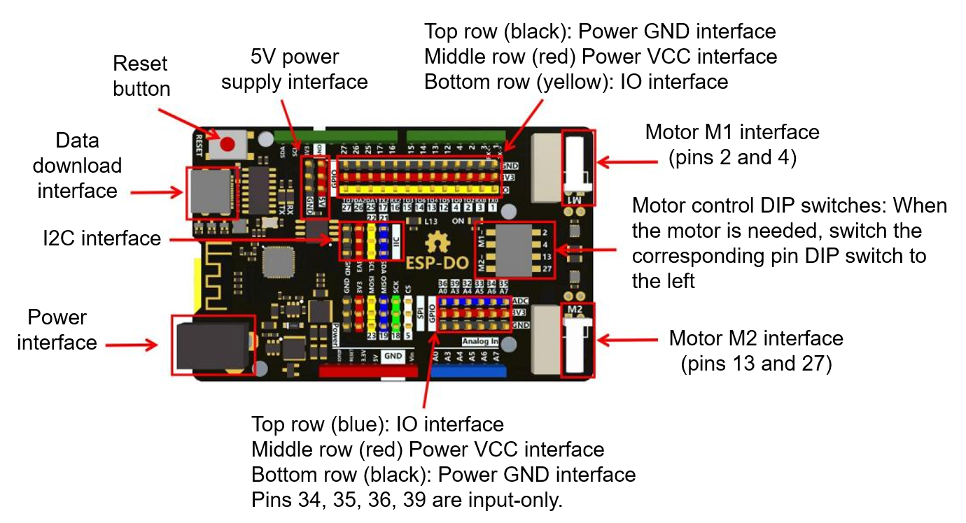
This project uses the ESP32 ESP-DO control board, which connects to a plethora of auxiliary devices to perform various actions. The specifics of the ESP-DO are as follows:
The project also includes a battery pack and charger as shown:
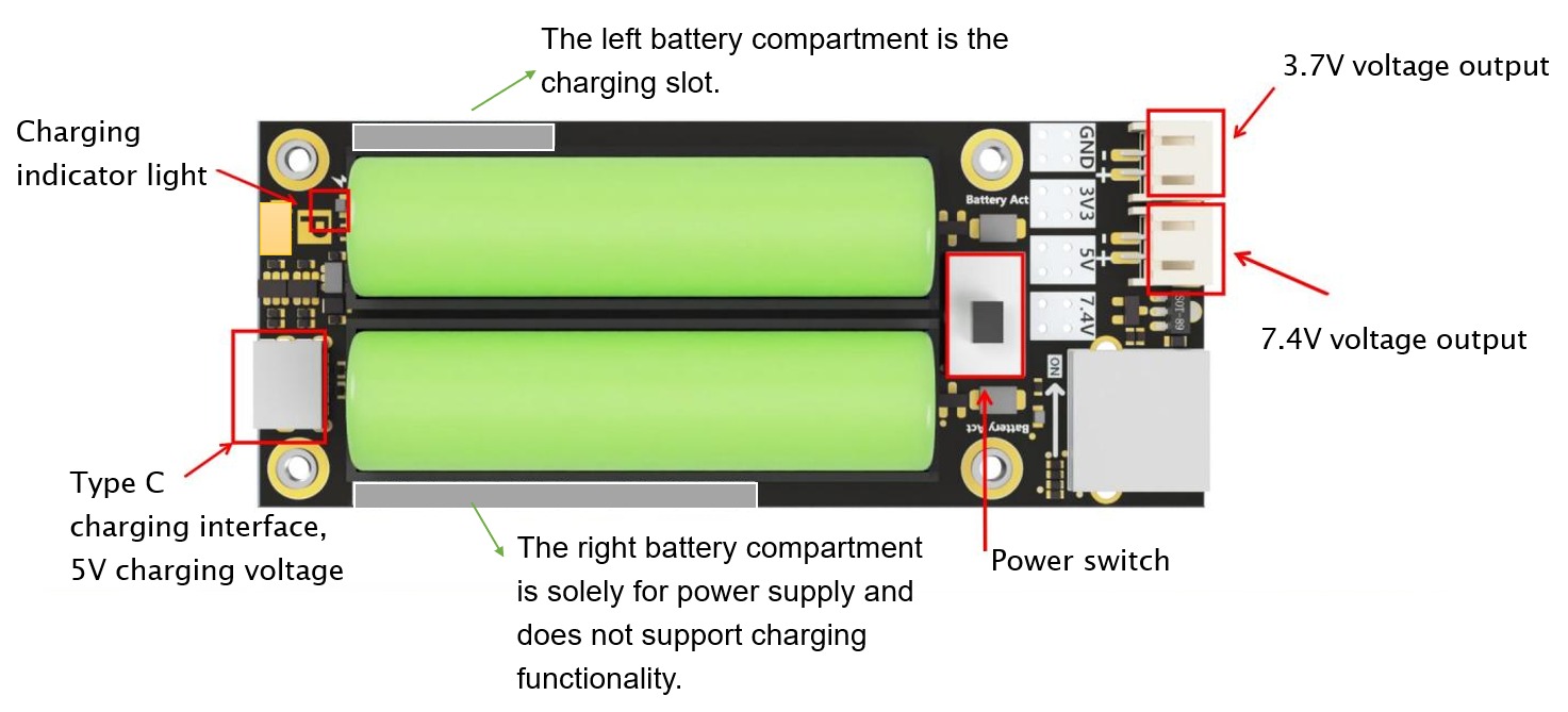
The power supply can only charge one battery at a time. When the charging indicator light goes out, it means the left battery is fully charged. Swap the positions of the two batteries and continue charging the other battery.
When using the mainboard motor drive, this power supply is required, and a 3.7V output is sufficient. Unplug the power cord when not in use.
Structural Assembly
The main structure consists of a number of wooden components and auxiliary devices. Below are the steps on how to properly assemble them into the Smart Kitchen model:
View Assembly Instructions
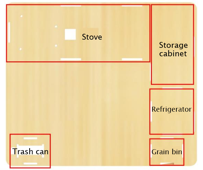
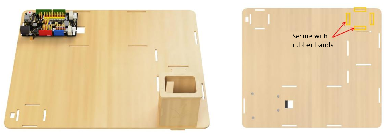
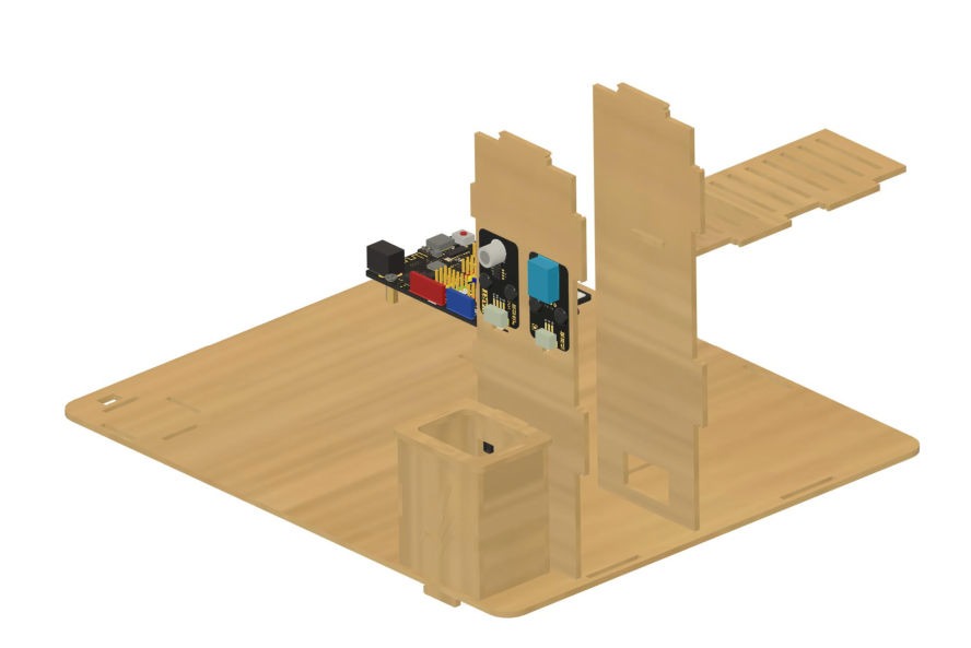
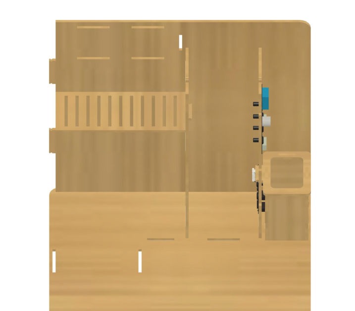
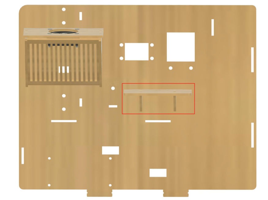
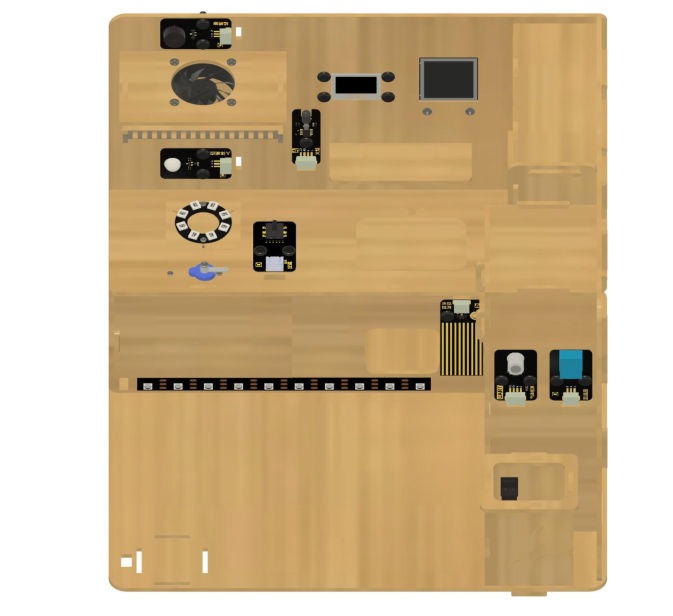
The structure will be laid out on the base plate (wooden board #1) in the following arrangement:
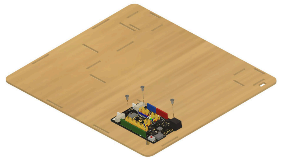
Screw 4 M3*6 screws into 4 brass spacers through the corresponding holes in the base plate (wooden board #1) as shown.

Secure the ESP-DO board to the brass spacers as shown using 3 additional M3*6 screws.
Take wooden boards #23, #24, #25, #26, and #27 and assemble them into the food storage bin structure, then insert it into the base plate as shown and secure the wooden tabs in place with rubber bands.
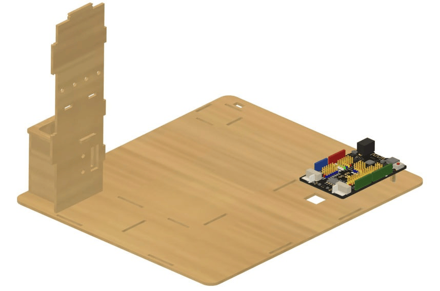
Take wooden board #8 and insert it into the base plate adjacent to the food storage bin, then insert the tab from the lid of the storage bin into the slot on board #8 as shown, securing it with a rubber band.
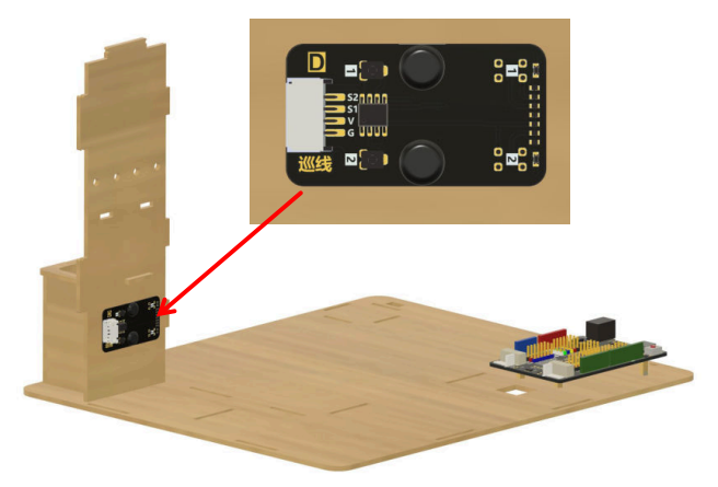
Take the line tracking module and plug in a 40cm 4-pin wire, place the module against board #8 as shown, and secure it in place with the black fasteners (note that these do not have to be screwed or separated in any ways, but simply pushed through the fastener holes).
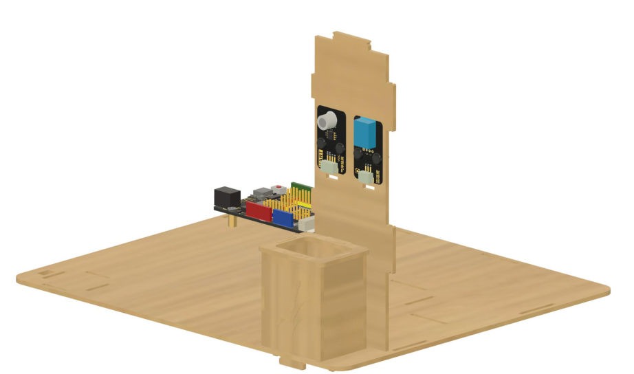
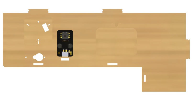
Install the VOC gas sensor and temperature/humidity sensor modules on the opposite side of board #8 as shown, and connect their wiring and secure them in place similarly to the line tracking module.
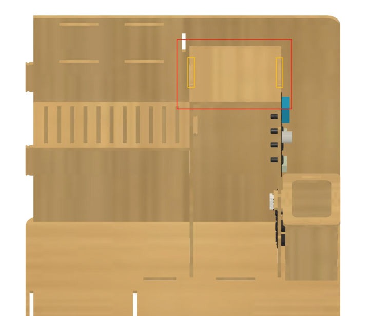
Take wooden board #7 and insert it into the base plate in the location shown, then connect wooden board #18 to the upper part of board #7 as pictured and secure with rubber bands.
Take wooden board #3 and insert it into the base plate as show, and connect the wooden tabs from boards #7, #8, and #18 to the corresponding slots on board #3. Secure the tabs on board #18 with rubber bands.
Take wooden board #10 and connect it to boards #7 and #8 by bridging them at the top, as shown in the picture. Secure the top tabs of boards #7 and #8 with rubber bands.
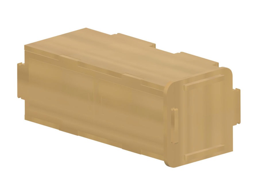
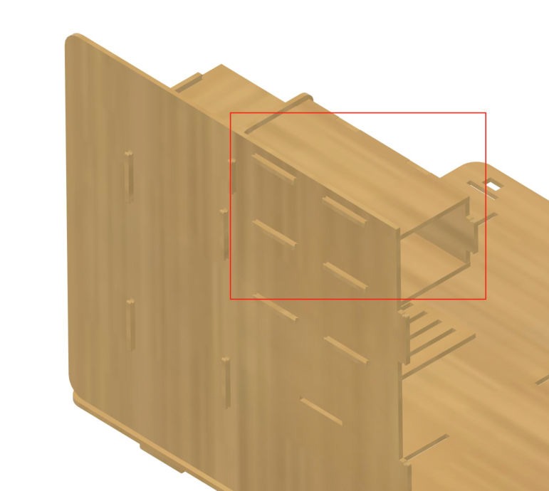
Take wooden boards #19, #20, #21, and #22 and assemble them into the structure shown below, and secure the wooden tabs to the end plate with rubber bands.
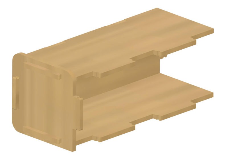
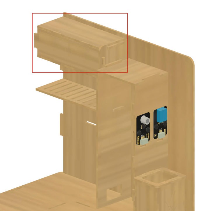
Attach this component to the main structure in the position shown and secure the wooden tabs on the back with rubber bands.
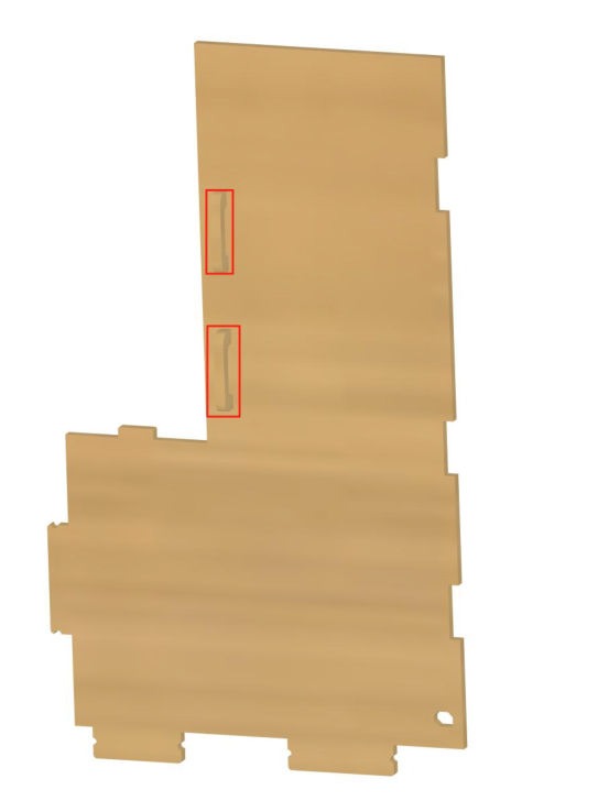
Take wooden board #9 and attach the two refrigerator handles in the configuration shown, securing them on the back with rubber bands.
Insert board #9 into the base plate at the front of the board #7-8-10 structure (the refrigerator body) as shown in the picture.
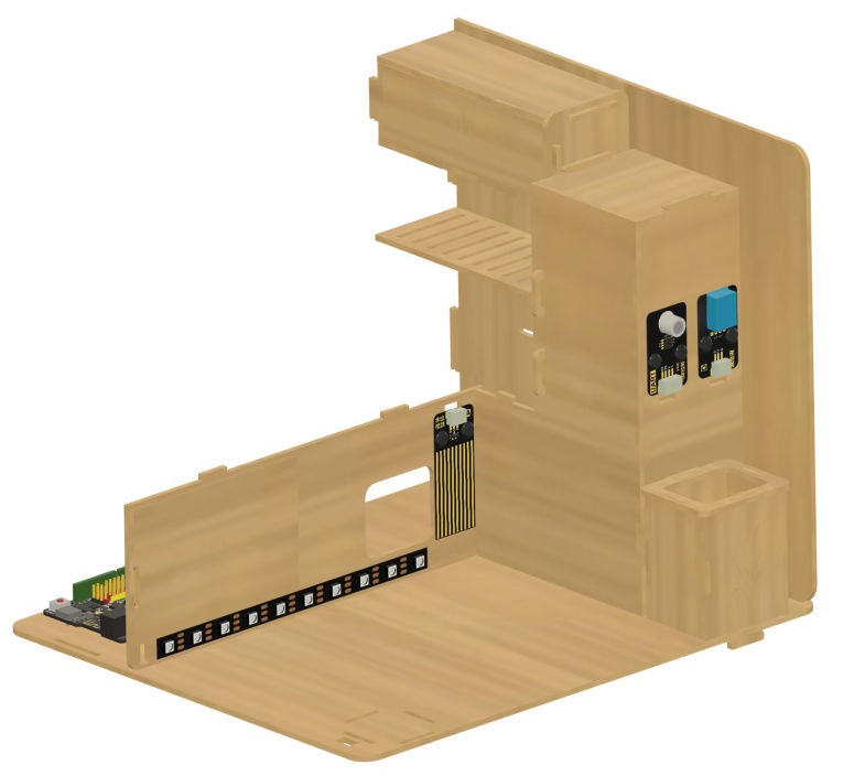
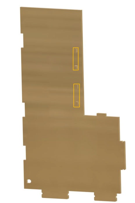
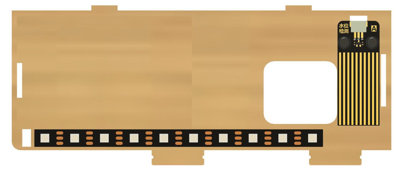
Take wooden board #5 and orient it as shown. Connect the water level sensor to a 20cm 3-pin wire and attach it to board #5 in the position as pictured, threading the cable through the cable hole, and using the black fasteners to secure it in place.
Attach the RGB light strip to board #5 in the position as pictured, threading the cable through the cable hole at the left end.
Insert board #5 into the base plate in the orientation shown, then attach wooden board #6 to its far end in the position shown and secure both in place with rubber bands.

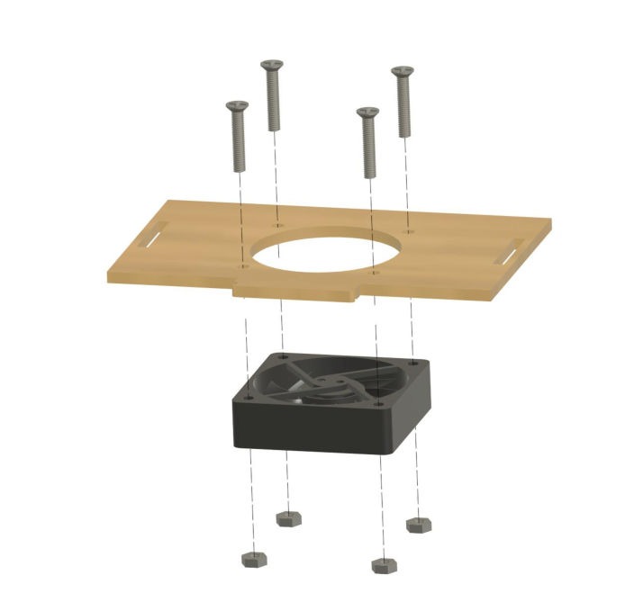
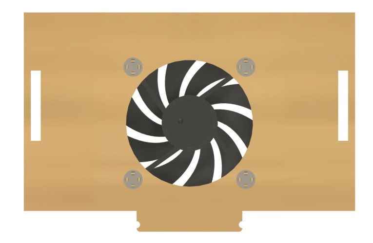
Take wooden board #14 and attach the fan module to it in the orientation shown, securing it in place with 4 M3*15 screws and M3 nuts.
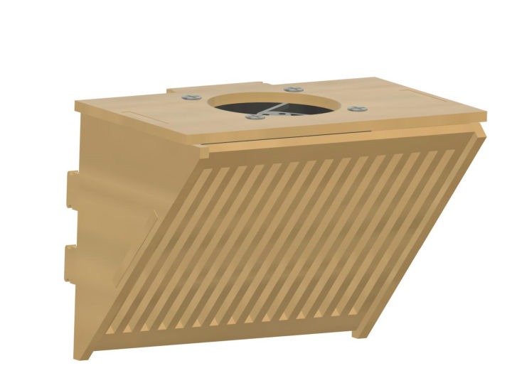
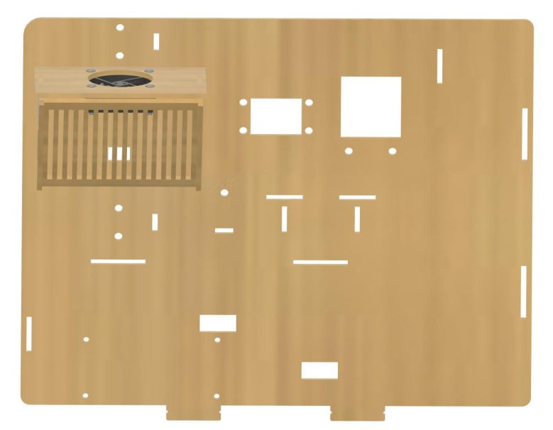
Take wooden boards #11, #12, and #13, and attach them to board #14 as shown to form the range hood assembly. Attach this assembly to wooden board #2 in the configuration pictured.
Take wooden boards #15, #16, and #17, and assemble them into the assembly shown in the image, then attach this assembly to board #2 in the position shown.

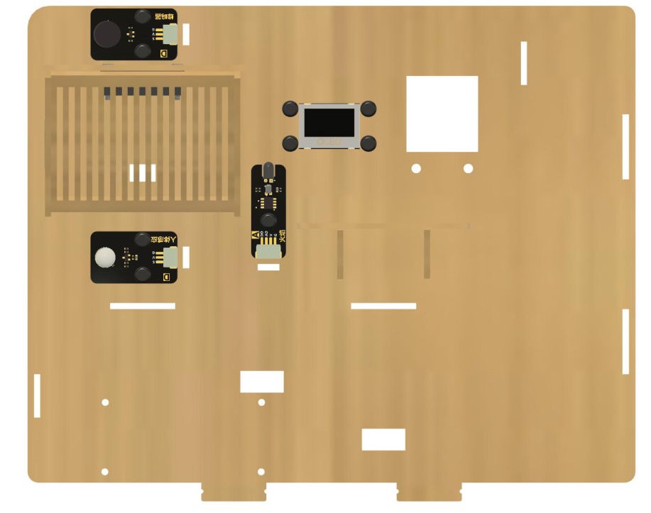
Take out the tone buzzer, OLED, flame sensor, and human motion sensor modules, and connect the corresponding wires:
- OLED display: 30cm 4-pin wire
- Tone buzzer: 30cm 3-pin wire
- Human motion sensor: 20cm 3-pin wire
- Flame sensor: 20cm 4-pin wire
Attach all modules to board #2 in the positions pictured, and use black fasteners to secure them in place.
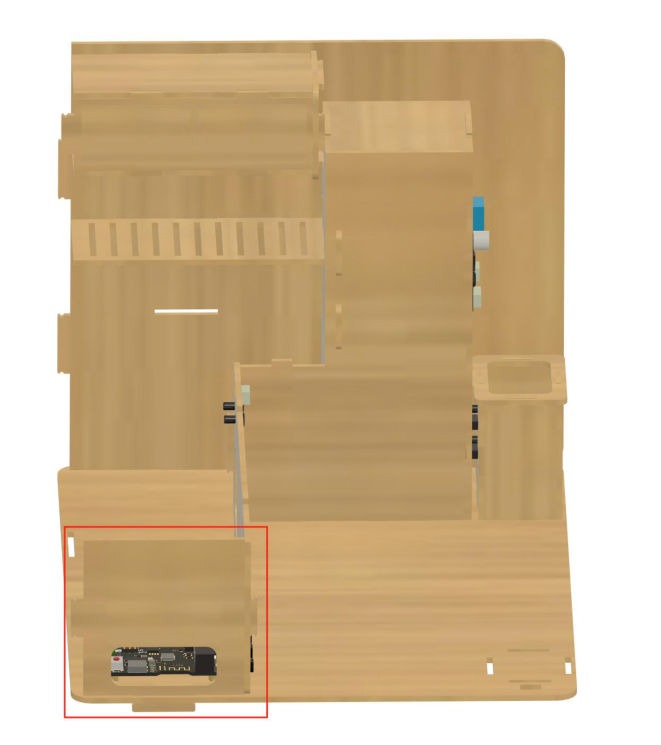
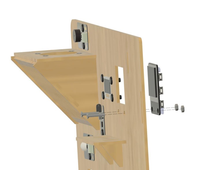
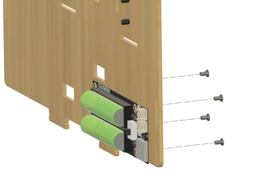
Attach the AI Smart Assistant module to the back of board #2 and secure it in place with M3*15 screws and nuts, then attach the battery module to the back of board #2 in the location shown and secure it in place with M3*6 screws.
Take out wooden board #4, and attach the 5-directional input module in the position shown, securing it in place with black fasteners.
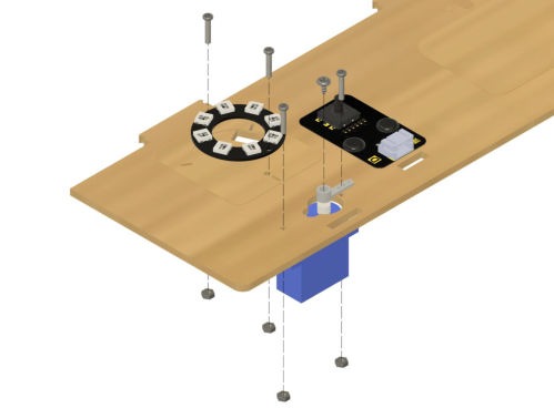
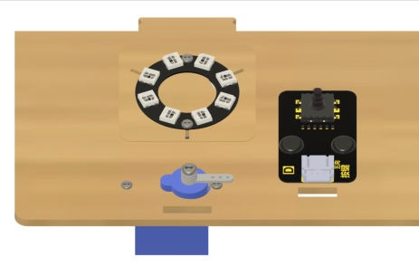
Attach the LED light ring and 180-degree servo in the positions shown adjacent to the 5-directional input module, using M2 screws and nuts to secure them in place.
M2 nut: 
M2 screw: 
Attach board #2 to the main structure and thread all remaining loose wires through the appropriate wire holes to connect them to the ESP-DO.
(Note: connecting the wiring to the correct pins can be done at a later stage, but for the sake of convenience do not secure any panels with wires that are still unconnected.)
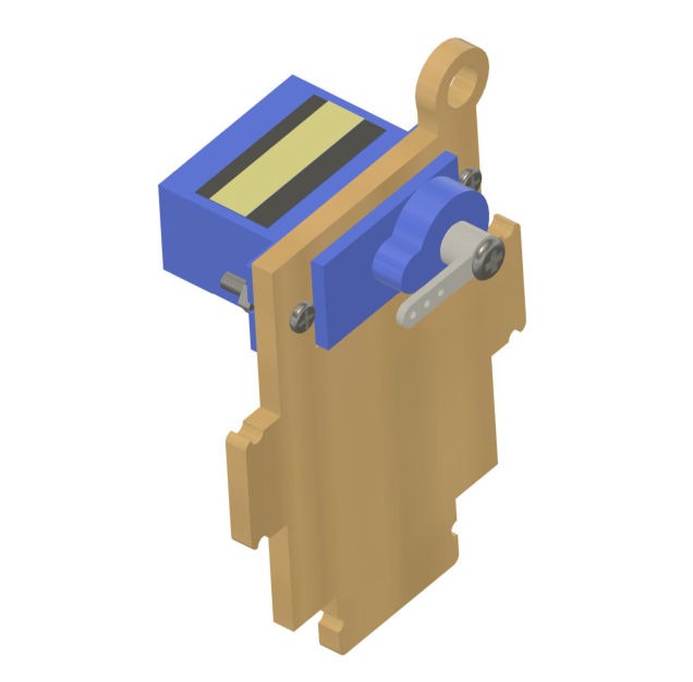
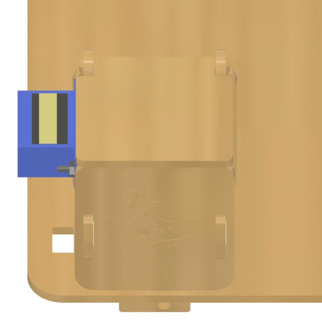
Take out wooden board #29 and use M2 screws to attach the 180-degree servo to the board in the configuration shown. Assemble board #29 with wooden boards #28, #30, #31, and #32 to form a trash can, then attach this trash can to the base plate and connect the servo wire through the wire hole to the control board.
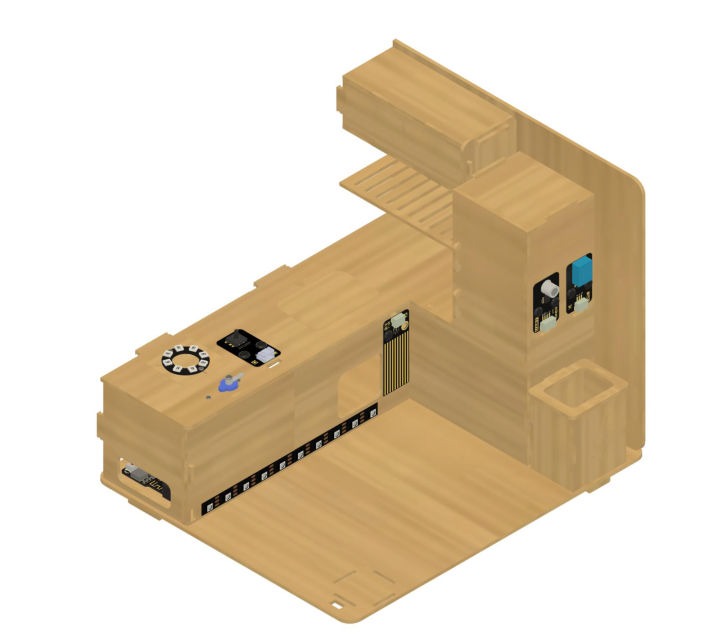
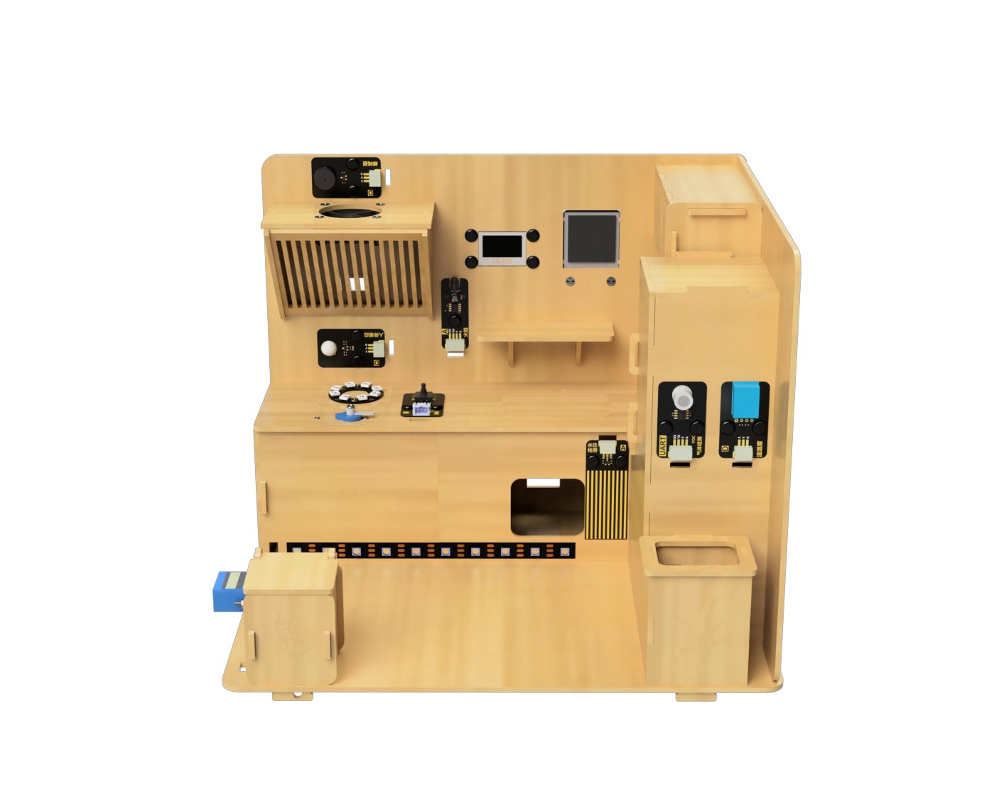
Completed Structure
Theme A: Atmosphere & Interface
Using lights, displays, and sounds to communicate system status to the user.
Goal
Understand how to use and control LED lighting.
Hardware and Wiring
- LED light strip - pin 12
- 5-way direction interface - pin 34
What You Do In Mind+
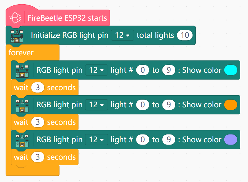
- Basic Lighting
- Initialize LED light strip on pin 12 with 10 total lights.
- In forever:
- Set all lights (index 0 to 9) to a certain color.
- Wait a period of time (e.g. 3 seconds), then change the lights to a different color.
- Repeat this for more colors as desired.
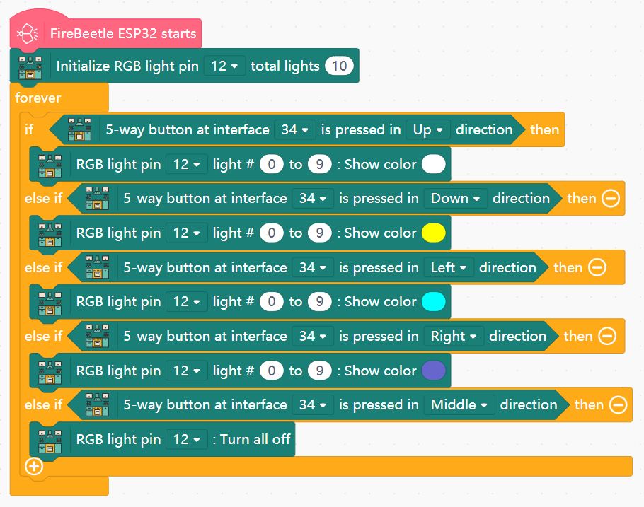
- Lighting Control
- In forever:
- Get the 5-way direction interface input from pin 34.
- Use an IF block to change the LED light strip's color based on the Up, Down, Left, and Right buttons being pressed.
- Have the light strip turn OFF if the Middle direction is pressed.
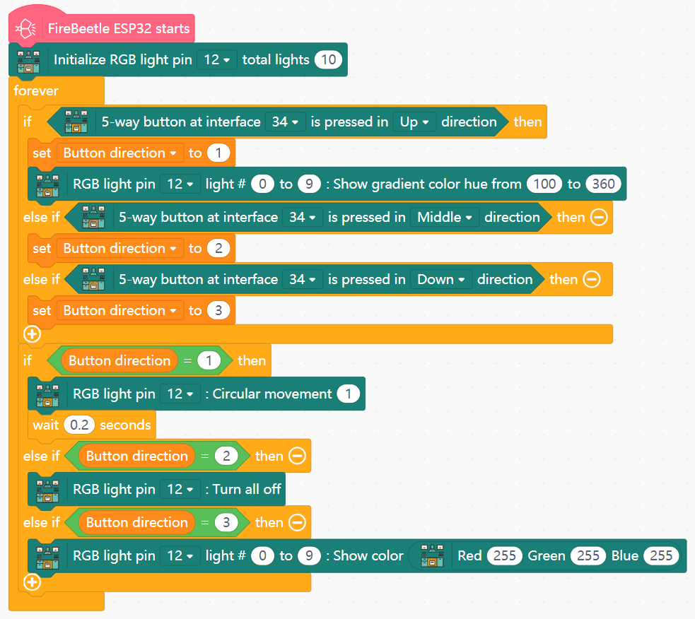
- Lighting Modes
- Create the variable
Button direction. - In forever:
- Use an IF block to perform the following actions upon directions being pressed:
- Up - set
Button directionto 1 and change the light strip to a gradient. - Middle - set
Button directionto 2. - Down - set
Button directionto 3.
- Up - set
- Use the value of
Button directionto dictate the following states:- If
Button direction= 1: Set LED light strip to perform circular movement with 0.2 second interval. - If
Button direction= 2: Turn all lights off. - If
Button direction= 3: Set all lights to white.
- If
- Use an IF block to perform the following actions upon directions being pressed:
View Sample Program
View Sample Program
View Sample Program
Goal
Understand how to use and control LED lighting.
Hardware and Wiring
- LED light ring - pin 13
- 5-way direction interface - pin 34
- 180-degree servo - pin 14
What You Do In Mind+
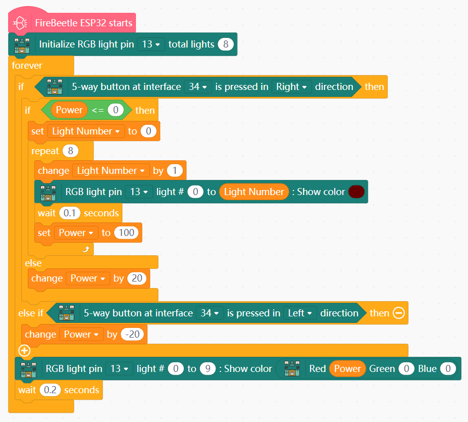
- Stove Ignition
- Create the variables
PowerandLight Number. - Initialize LED light ring on pin 13 with 8 total lights.
- In forever:
- Create an IF block to perform actions when the Right direction is pressed on the direction interface:
- If
Power≤ 0 (stove is off): fire up the lights in quick succession and setPowerto 100. - Otherwise, increase
Powerby 20.
- If
- If the Left direction is pressed, decrease
Powerby 20. - Set the light ring to shine a red color with intensity dictated by the value of
Power.
- Create an IF block to perform actions when the Right direction is pressed on the direction interface:
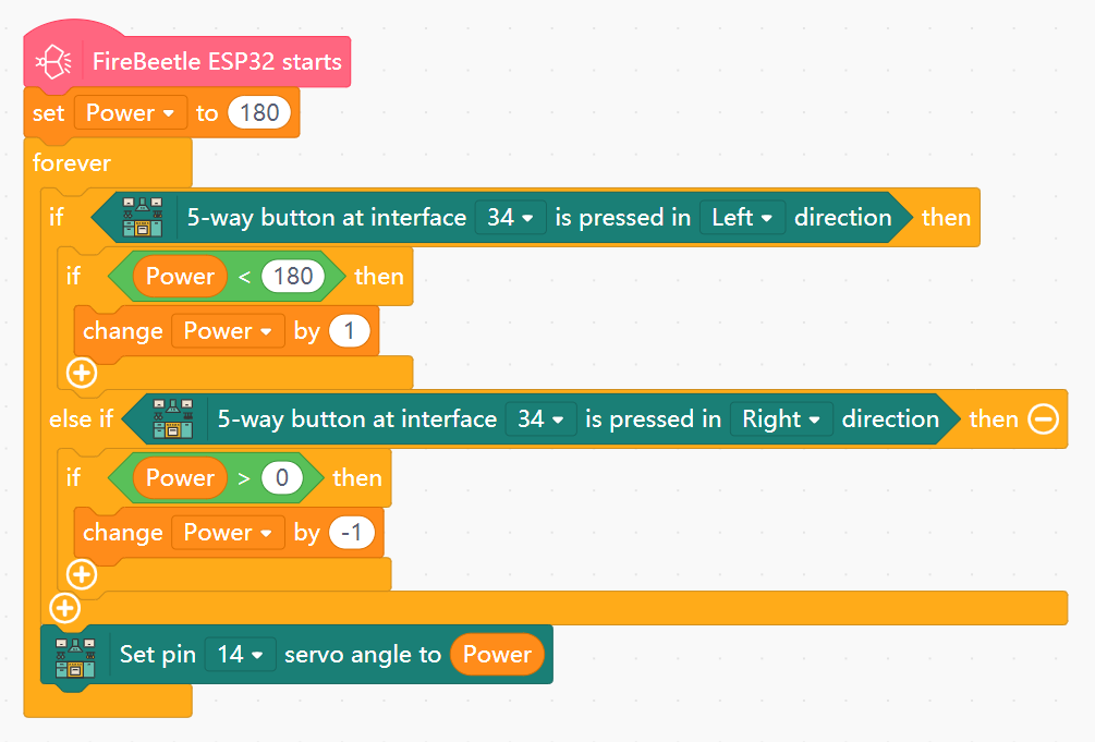
- Power Gauge
- Create the variable
Powerwith initial value 180. - In forever:
- Use an IF block to increase
Powerby 1 if the Left direction is pressed andPower< 180. - Use an IF block to decrease
Powerby1 if the Right direction is pressed andPower> 0. - Set the angle of the servo (pin 14) to the value of
Power.
- Use an IF block to increase
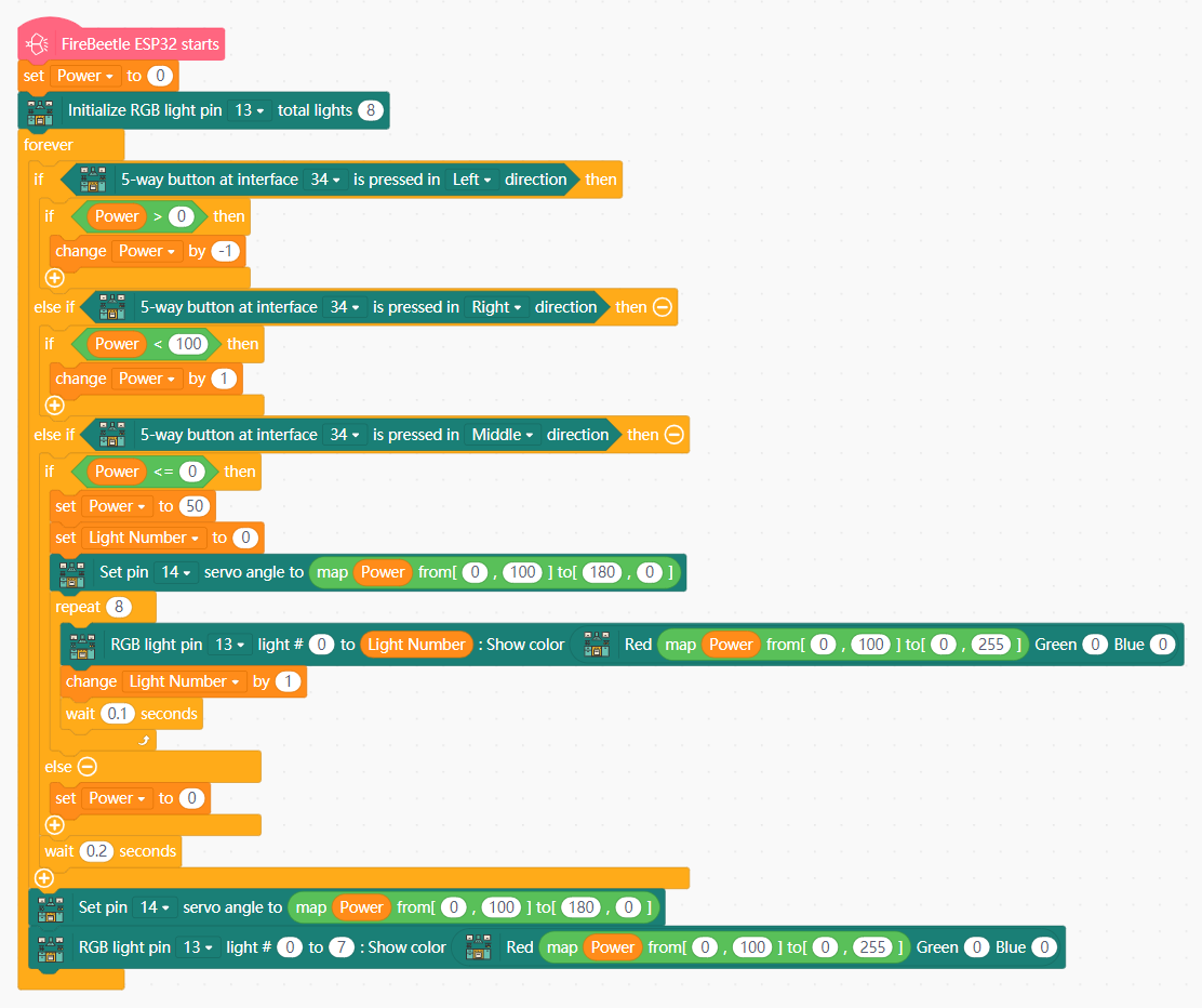
- Stove Heat Adjustment
- Create the variables
PowerandLight Number. - In forever:
- Use an IF block to:
- Decrease
Powerby 1 when Left direction is pressed. - Increase
Powerby 1 when the Right direction is pressed. - Set functional minimum and maximum values of
Powerat 0 and 100 respectively.
- Decrease
- Use another IF block to power on the stove when the Middle direction is pressed, with an initial
Powervalue of 50. - Set the LED light ring to Red with the value of
Power(0-100) mapping to the brightness value (0-255). - Set the angle of the servo (180-0) based on an inverse mapping with the value of
Power(0-100).
- Use an IF block to:
View Sample Program
View Sample Program
View Sample Program
Goal
Understand how to activate and control range hood ventilation.
Hardware and Wiring
- 5-way direction interface - pin 34
- Fan module - motor M1-The range hood can operate normally only when both batteries are at full charge
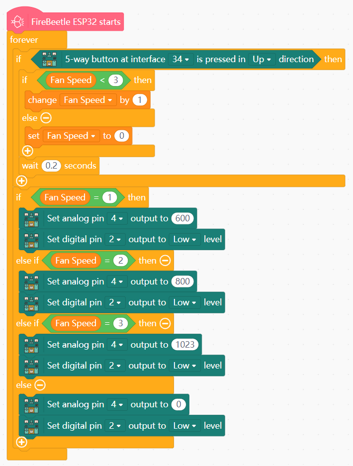
What You Do In Mind+
- Create the variable
Fan Speed. - In forever:
- Use an IF block to make pressing the Up direction cycle through
Fan Speedvalues 0, 1, 2, and 3. - Use another IF block to set the actual fan speed based on the state (value) of
Fan Speed:Fan Speed= 1: set fan speed (pin 4) to 600.Fan Speed= 2: set fan speed to 800.Fan Speed= 3: set fan speed to 1000.- Else: set fan speed to 0.
- Use an IF block to make pressing the Up direction cycle through
View Sample Program
Goal
Understand how to use and control the OLED screen and tone emitter.
Hardware and Wiring
- LED light ring - pin 13
- 5-way direction interface - pin 34
- Fan module - motor The range hood can operate normally only when both batteries are at full charge
- OLED screen - I2C interface
- Tone buzzer - pin 25
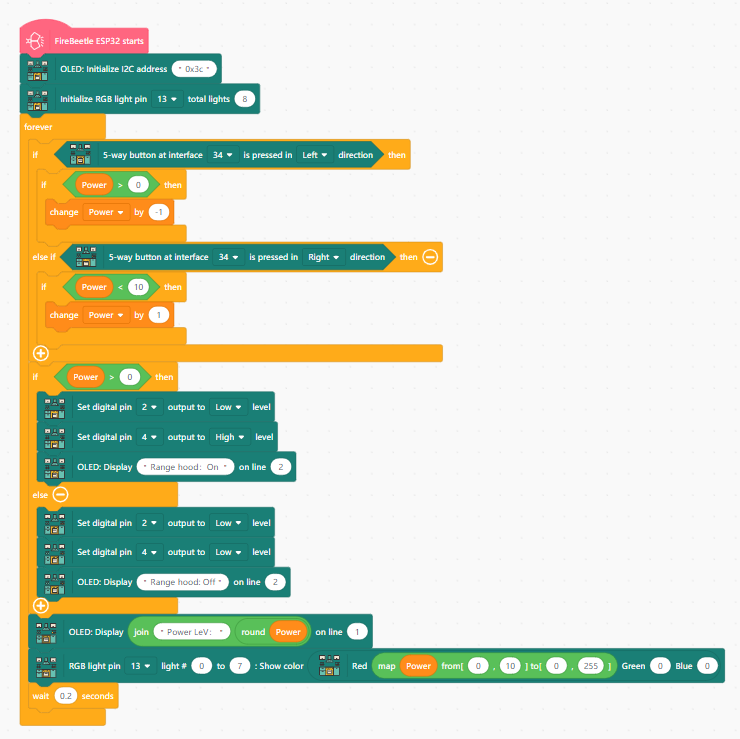
What You Do In Mind+
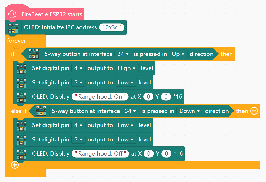
- Display Screen
- Initialize the OLED with I2C address 0x3c.
- In forever:
- Create an IF block to perform actions when the Up direction is pressed on the direction interface:
- Set fan output (pin 4) to High.
- Display "Range hood: On" on the OLED.
- Create an IF block to perform actions when the Down direction is pressed on the direction interface:
- Set fan output to Low.
- Display "Range hood: Off" on the OLED.
- Set the value of pin 2 to Low in all instances.
- Create an IF block to perform actions when the Up direction is pressed on the direction interface:
- Flame Power Display
- Initialize LED light ring on pin 13 with 8 total lights.
- Create the variable
Power. - In forever:
- Use an IF block to:
- Decrease
Powerby 1 when Left direction is pressed. - Increase
Powerby 1 when the Right direction is pressed. - Set functional minimum and maximum values of
Powerat 0 and 10 respectively.
- Decrease
- Create an IF block to perform actions when the Up direction is pressed on the direction interface:
- Set fan output (pin 4) to High.
- Display "Range hood: On" on OLED line 2.
- Create an IF block to perform actions when the Down direction is pressed on the direction interface:
- Set fan output to Low.
- Display "Range hood: Off" on OLED line 2.
- Set the value of pin 2 to Low in all instances.
- Display "Power LeV:" with the value of
Poweron OLED line 1. - Set the LED light ring to Red with the value of
Power(0-10) mapping to the brightness value (0-255).
- Use an IF block to:
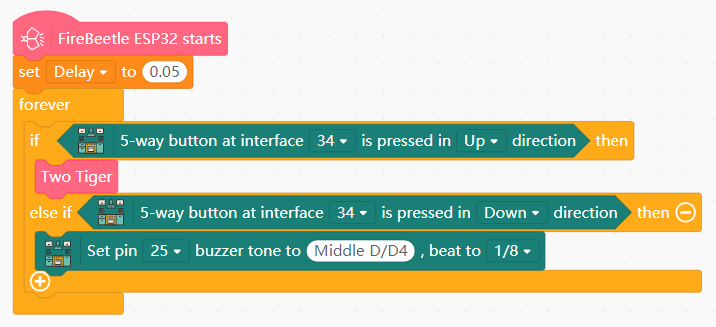
- Playing Tones
- Create the variable
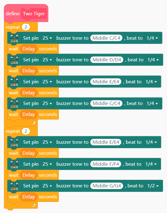
Delaywith initial value 0.05. - Create a new function with any name (example named "Two Tiger" after the tune it plays), containing the following:
- Set the buzzer (pin 25) to play a given tone, followed by a pause of
[Delay]seconds. - Chain together different notes as desired, separated by
Delaypauses, and optionally using loops or repeats.
- Set the buzzer (pin 25) to play a given tone, followed by a pause of
- In forever:
- Use an IF block to call your function if the Up direction is pressed on the direction interface.
- Use another IF block to play a flat tone if the Down direction is pressed.
View Sample Program
View Sample Program
View Sample Program
Theme B: Hazard Detection & Safety
Implementing sensor-based "Watchdogs" to prevent accidents.
Goal
Set up a system to detect gas leaks and alert the user.
Hardware and Wiring
- LED light strip - pin 12
- Tone buzzer - pin 25
- VOC sensor - TX Pin on the Sensor to pin 26
- OLED screen - I2C interface
What You Do In Mind+
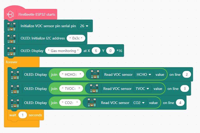
- Gas Leak Detection
- Initialize the VOC sensor on pin 26.
- Initialize the OLED with I2C address 0x3c and display the text "Gas Monitoring:" on line 1.
- In forever:
- Display "HCHO:" and the HCHO value from the VOC sensor on line 2.
- Repeat the above operation and place the titles and values of flammable gas (TVOC) and carbon dioxide (CO2) in the third and fourth lines respectively.
- Add a 1-second buffer at the end.
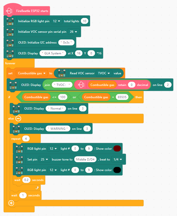
- Gas Leak Alarm
- Create the variable
Combustible gas. - Initialize the LED light strip on pin 12 with 10 lights.
- Initialize the tone buzzer on pin 25.
- Initialize the OLED and display the text "GLA System" (Gas Leak Alarm) on line 1.
- In forever:
- Read the TVOC value from the VOC to
Combustible gas. - Display the value of
Combustible gason OLED line 2. - Display the following on line 3:
- If
Combustible gas< 100 (or an underflow value), display "Normal". - Else, display "WARNING", and flash the lights (pin 12) and play a warning tone (pin 25).
- If
- Add a 1-second buffer at the end.
- Read the TVOC value from the VOC to
View Sample Program
View Sample Program
Goal
Learn how to set up fire alarms and water level sensors.
Hardware and Wiring
- LED light strip - pin 12
- Tone buzzer - pin 25
- Water level sensor - pin 33
- IR fire detector - pin 35
- OLED screen - I2C interface
What You Do In Mind+
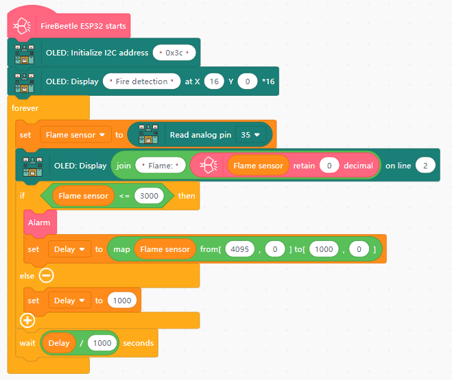
- Fire Detection
- Create the variables
Flame sensorandDelay. - Initialize the OLED with I2C address 0x3c and display the text "Fire Detection" on line 1.
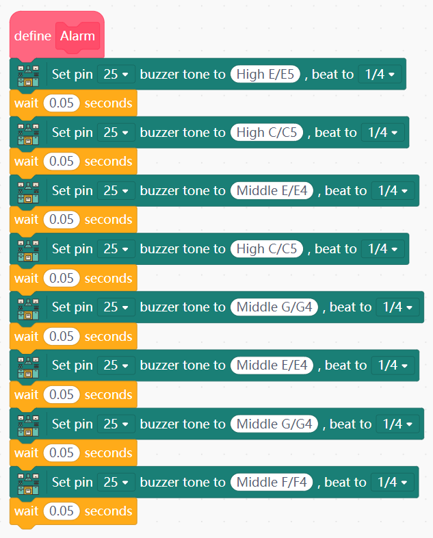
- Create a function with a unique name (e.g. "Alarm Sound) that contains the following:
- Have the tone buzzer (pin 25) play a given tone.
- Chain together a number of different tones (separated by 0.05 second delay) to create an alarm sound.
- In forever:
- Read the value of the fire detector (pin 35) into
Flame sensor. - Display "Flame sensor:" and the value of
Flame sensoron OLED line 2. - If
Flame sensor≤ 3000, call your function and map the value ofFlame sensor(4095-0) to the value ofDelay(1000-0). - Wait for
[Delay]milliseconds (orDelay/ 1000 seconds).
- Read the value of the fire detector (pin 35) into
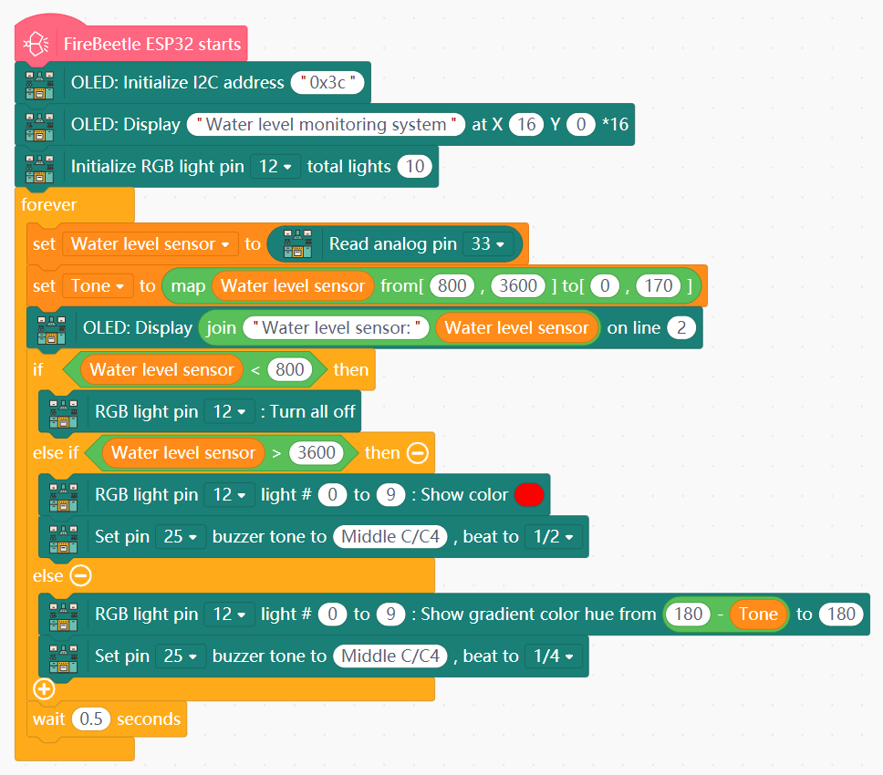
- Water Level Monitoring
- Create the variables
Water level sensorandTone. - Initialize the LED light strip on pin 12 with 10 lights.
- Initialize the OLED and display the text "Water level monitoring system" on line 1.
- In forever:
- Read the value from the water level sensor (pin 33) to
Water level sensor. - Map the value of
Water level sensor(800-3600) toTone(0-170). - If
Water level sensor< 800, turn off the LED light strip (pin 12). - If
Water level sensor> 3600, set the LED light strip to Red and play a tone. - Else, display a color gradient ranging from (
Tone-180) to 180 and play the tone at different timing. - Add a 0.5-second buffer at the end.
- Read the value from the water level sensor (pin 33) to
View Sample Program
View Sample Program
Goal
Design a system that automatically turns off the stove after human inactivity.
Hardware and Wiring
- LED light ring - pin 13
- Human motion sensor - pin 32-The human body induction module must wait for 2 minutes to work properly.
- 5-way direction interface - pin 34
What You Do In Mind+
- Create the variables
Start TimeandFire. SetStart Timeinitial value to 0. - Initialize LED light ring on pin 13 with 8 total lights.
- In forever:
- Set
Fireto 0 if the 5-way direction pad is pressed Left, and 1 if it is pressed Right. - If
Fire= 1:- Set the LED light ring to Red.
- When no humans are detected (human sensor value from pin 32 = 0), read the current time into
Start Time. - If the difference between current time and
Start Timeexceeds 5 seconds, setFireandStart Timeto 0.
- Else: Turn off the LED light ring.
- Add a 0.2-second buffer at the end.
- Set
View Sample Program
Theme C: Storage & Maintenance
Smart management of resources and equipment health.
Goal
Design a trash can that responds to user inputs.
Hardware and Wiring
- 180-degree servo - pin 15
- 5-way direction interface - pin 34
What You Do In Mind+
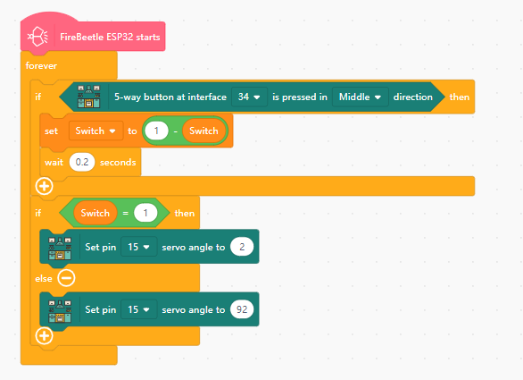
- In forever, if the 5-way direction pad (pin 34) is pressed in the Middle direction:
- Toggle the
Switchvariable - If
Switch= 1 : Set pin 15 servo angle to 2. - Else: Set pin 15 servo angle to 92.
View Sample Program
Goal
Set up a system to monitor food freshness in the refrigerator.
Hardware and Wiring
- LED light strip - pin 12
- Tone buzzer - pin 25
- VOC sensor - TX Pin on the Sensor to pin 26
- DHT11 temperature/humidity sensor - pin 27
- Human motion sensor - pin 32-The human body induction module must wait for 2 minutes to work properly
- OLED screen - I2C interface
What You Do In Mind+
- Temperature and Humidity Detection
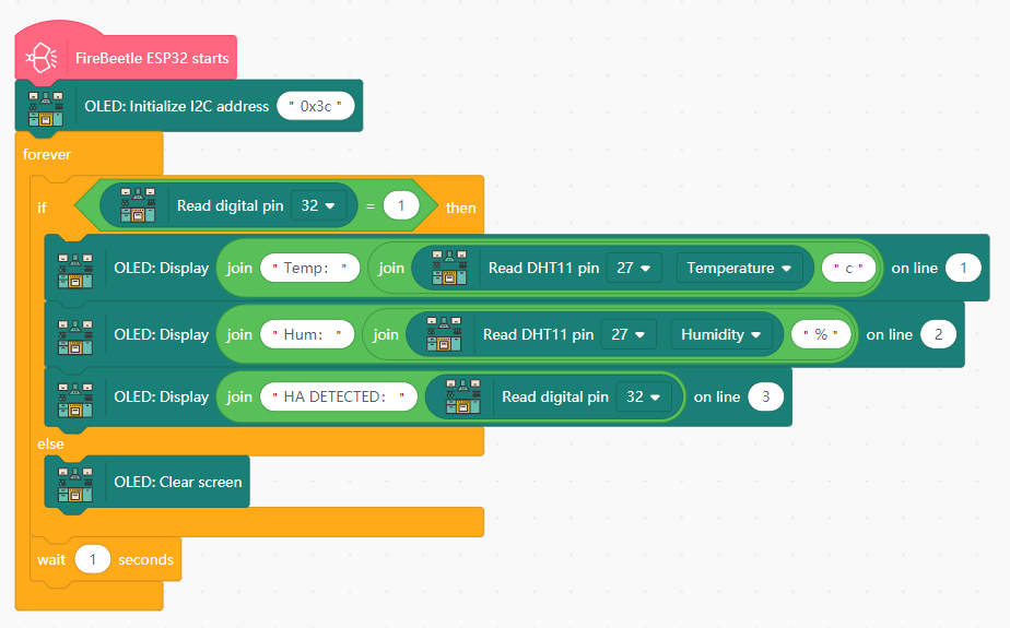
- Initialize the OLED with I2C address 0x3c.
- In forever:
- Create an IF block to perform actions when a human is detected (pin 32 value = 1):
- Display the text "Temp:" and the temperature value from the DHT11 sensor (pin 27) on OLED line 1.
- Display the text "Hum:" and the humidity value from the DHT11 sensor on OLED line 2.
- Display the text "HA DETECTED:" and the value from the human motion sensor on OLED line 3.
- Else: Clear the OLED screen.
- Add a 1-second buffer at the end.
- Create an IF block to perform actions when a human is detected (pin 32 value = 1):
- Freshness Testing
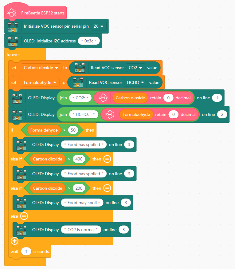
- Initialize VOC sensor on pin 26.
- Create the variables
Carbon dioxideandFormaldehyde. - In forever:
- Set
Carbon dioxidevalue to the CO2 value from the VOC sensor (pin 26). - Set
Formaldehydevalue to the HOHC value from the VOC sensor. - Display "CO2:" and the value of
Carbon dioxideon OLED line 1. - Display "HCHO:" and the value of
Formaldehydeon OLED line 2. - Display the following text on OLED line 3:
- If
Formaldehyde> 50 ORCarbon dioxide> 400: display "Food has spoiled". - Else if
Carbon dioxide> 200: display "Food may spoil". - Else: display "CO2 is normal".
- If
- Add a 1-second buffer at the end.
- Set
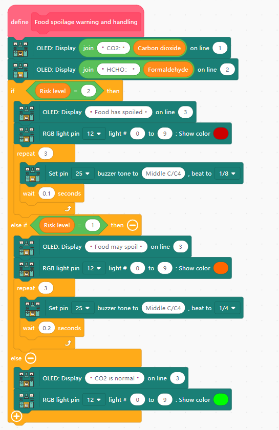
- Food Spoilage Warning
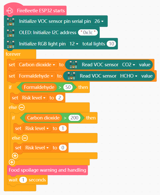
- Create the variables
Carbon dioxide,Formaldehyde, andRisk level. - Initialize LED light strip on pin 12 with 10 lights.
- Create a new function with the name "Food spoilage warning and handling", containing the following:
- Display "Carbon dioxide:" and the value of
Carbon dioxideon OLED line 1. - Display "Formaldehyde:" and the value of
Formaldehydeon OLED line 2. - If
Risk level= 2:- Display "Food has spoiled" on OLED line 3.
- Set the LED light strip (pin 12) to Red.
- Have the buzzer (pin 25) play a tone 3 times in rapid succession.
- If
Risk level= 1:- Display "Food may spoil" on OLED line 3.
- Set the LED light strip to Orange.
- Have the buzzer play a tone 3 times at moderate speed.
- Else:
- Display "CO2 is normal" on OLED line 3.
- Set the LED light strip to Green.
- Display "Carbon dioxide:" and the value of
- In forever:
- Set
Carbon dioxidevalue to the CO2 value from the VOC sensor (pin 26). - Set
Formaldehydevalue to the HOHC value from the VOC sensor. - If
Formaldehyde> 50: setRisk levelto 2. - Else if
Carbon dioxide> 200: setRisk levelto 1. - Else: set
Risk levelto 0. - Call your food spoilage warning function.
- Add a 1-second buffer at the end.
- Set
View Sample Program
View Sample Program
View Sample Program
Goal
Create a loose food storage that can actively track and notify the user of the amount of food stored.
Hardware and Wiring
- LED light strip - pin 12
- Dual-line tracking module - pins 19 (S2) and 23 (S1) -It is necessary to connect a 5V power supply.
- Human motion sensor - pin 32-The human body induction module must wait for 2 minutes to work properly
- OLED screen - I2C interface
- Ps:If the dual line-tracking module triggers an anomaly, manually adjust the threshold. Use a screwdriver to adjust the knobs behind S1 and S2 until the lights turn off when not triggered and turn on when triggered.
What You Do In Mind+
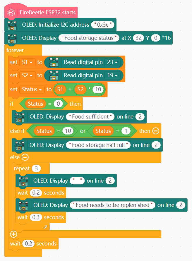
- Food Inventory Status
- Create the variables
S1,S2, andStatus. - Initialize the OLED with I2C address 0x3c and display "Food storage status" on line 1.
- In forever:
- Read the value of S1 (pin 23) into
S1and S2 (pin 19) intoS2. - Set the value ot
StatustoS1+ (S2* 10). - Create an IF block to display the following text on line 2:
- If
Status= 0: display "Food sufficient" - If
Status= 10 or 1: display "Food storage half full - Else: flash the text "Food needs to be replenished" on the OLED screen 3 times.
- If
- Add a 0.2-second buffer at the end.
- Read the value of S1 (pin 23) into
- Replenishment Reminder
- Initialize LED light strip on pin 12 with 10 lights.
- Create the variables
S1andS2. - In forever:
- Read the value of S1 (pin 23) into
S1and S2 (pin 19) intoS2. - If a human is detected (pin 32 value = 1) do the following:
- Display "Food storage status" on line 1.
- If
S1= 0 ANDS2= 0: display "Food sufficient" on OLED line 2 and set LED light strip (pin 12) to Green. - Else if
S1ORS2= 0 : display "Food storage half full" on OLED line 2 and set the first 6 LED lights to Orange, leaving the rest dark. - Else: flash the text "Food needs to be replenished" on the line 2 of the OLED screen 3 times, and set the first 3 LED lights to Red, leaving the rest dark.
- Add a 1-second buffer at the end.
- Read the value of S1 (pin 23) into
View Sample Program
View Sample Program

Goal
Design a cleaning reminder system for the range hood.
Hardware and Wiring
- Fan module - motor M1-The range hood can operate normally only when both batteries are at full charge
- 5-way direction interface - pin 34
- OLED screen - I2C interface
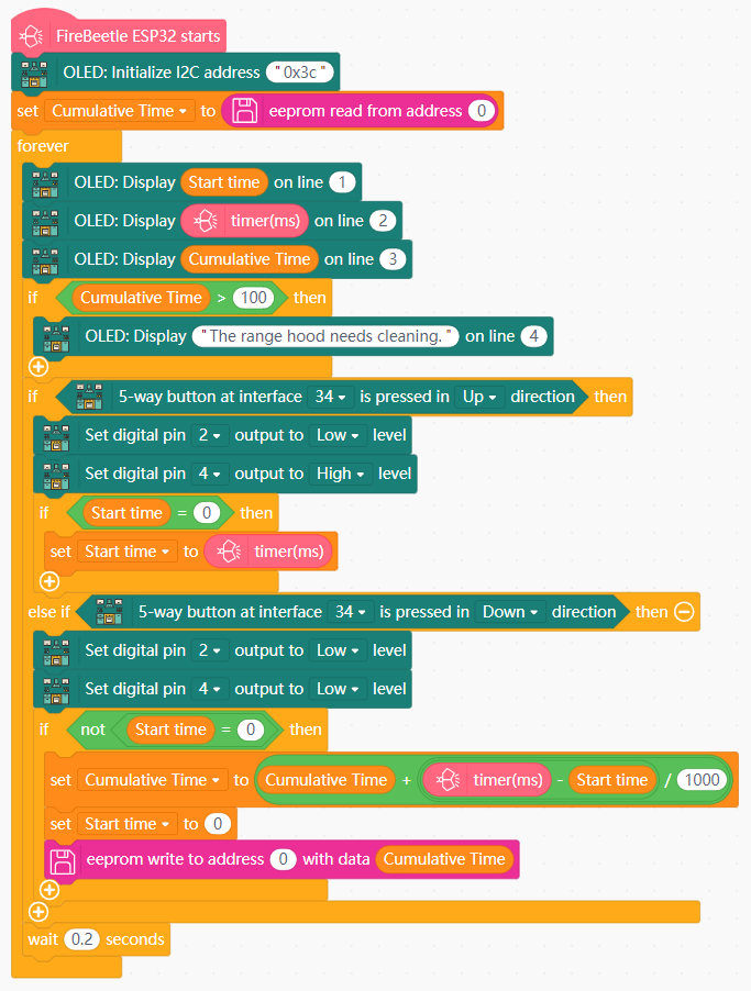
What You Do In Mind+
- Create the variables
Start timeandCumulative time. - Set
Cumulative timeto read the value from EEPROM address 0. - In forever:
- Display
Start timeon OLED line 1, the timer value (ms) on OLED line 2, andCumulative timeon OLED line 3. - If
Cumulative time> 100, display "The range hood needs cleaning" on OLED line 4. - If the 5-way directional interface is pressed in the Up direction:
- Turn on the fan (set pin 2 to Low and pin 4 to High).
- If
Start time= 0, setStart timeto the current timer value (ms).
- Else if the 5-way directional interface is pressed in the Down direction:
- Turn off the fan (set pin 2 and pin 4 to Low).
- If the value of
Start timeis not 0:- Set
Cumulative timeto (Cumulative time+ (timer value (ms) -Start time)/1000). - Set
Start timeto 0. - Save the value of
Cumulative timeto EEPROM address 0.
- Set
- Add a 0.2-second buffer at the end.
- Display
View Sample Program
Theme D: AI & Integrated System
Using Large Language Models (LLM) for natural interaction and system-wide control.
Goal
Use AI to enhance the cooking experience in the Smart Kitchen.
Hardware and Wiring
- LED light strip - pin 12
- LED light ring - pin 13
- 180-degree servo (stove) - pin 14
- 180-degree servo (trash) - pin 15
- XiaoZhi AI module - pins 16 (wire 38) and 17 (wire 39) -It is necessary to connect a 5V power supply.
- DHT11 temperature/humidity sensor - pin 27
- 5-way direction interface - pin 34
- OLED screen - I2C interface
What You Do In Mind+
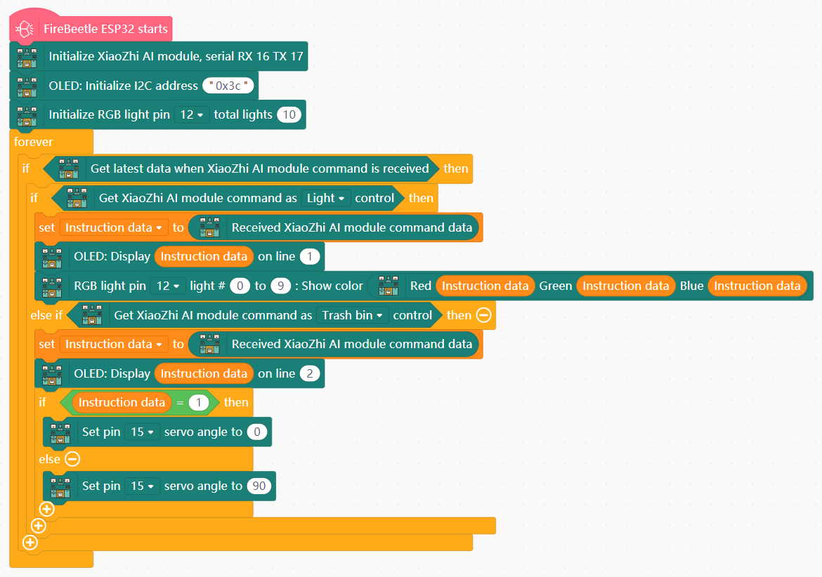
- AI-Controlled Devices
- Create the variable
Instruction data. - Initiate the LED light strip on pin 12 with 10 lights.
- Initiate the XiaoZhi AI module on pins 16 and 17.
- Initialize the OLED with I2C address 0x3c.
- In forever:
- Get the latest data from the AI module.
- Store the received AI module command data in
Instruction data. - If the AI module issues a command for the lights:
- Display
Instruction dataon OLED line 1. - Light the LED light strip (pin 12) based using
Instruction datafor RGB values.
- Display
- Else if the AI module issues a command for the trash bin:
- Display
Instruction dataon OLED line 2. - If
Instruction data= 1, set the angle of the servo motor (pin 15) to 0. Otherwise, set the angle to 90.
- Display
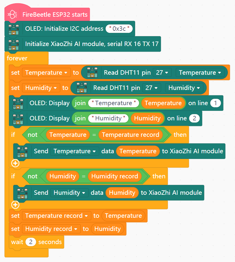
- Temperature Data Handling
- Create the variables
Temperature,Humidity,Temperature record, andHumidity record. - In forever:
- Set
TemperatureandHumidityvalues to the Temperature and Humidity values from the DHT11 sensor (pin 27). - Display "Temperature:" and the
Temperaturevalue on OLED line 1. - Display "Humidity:" and the
Humidityvalue on OLED line 2. - If
Temperature=/=Temperature record, send the data fromTemperatureto the AI module. - If
Humidity=/=Humidity record, send the data fromHumidityto the AI module. - Set the value of
Temperature recordtoTemperature, and set the value ofHumidity recordtoHumidity. - Add a 2-second buffer at the end.
- Set
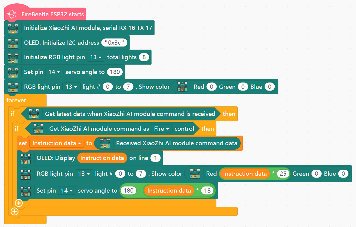
- Stove Flame Adjustment
- Create the variable
Instruction data. - Initialize the LED light ring on pin 13 with 8 lights, and set its initial state to 0.
- Set the 180-degree servo angle (pin 14) to 180.
- In forever:
- Get the latest data from the AI module, and store the command data in
Instruction data. - If the AI module issues a command for Fire:
- Display
Instruction dataon OLED line 1. - Set the Red value of the LED light ring (pin 13) to
Instruction data* 25. - Set the servo angle (pin 14) to (180 - (
Instruction data* 18)).
- Display
- Get the latest data from the AI module, and store the command data in
View Sample Program
View Sample Program
View Sample Program
Goal
Use AI to enhance the cooking experience in the Smart Kitchen.
Hardware and Wiring
- LED light ring - pin 13
- 180-degree servo (stove) - pin 14
- XiaoZhi AI module - pins 16 (wire 38) and 17 (wire 39)-It is necessary to connect a 5V power supply.
- Tone buzzer - pin 25
- Fan module - motor M1 -The range hood can operate normally only when both batteries are at full charge.
- OLED screen - I2C interface
What You Do In Mind+
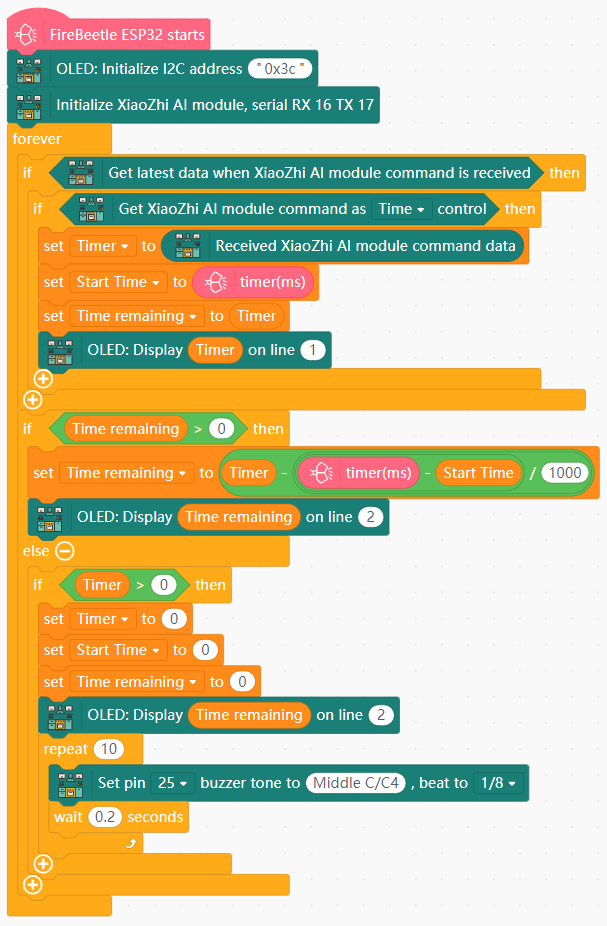
- AI-Powered Timer
- Create the variables
Timer,Start time, andTime remaining. - Initiate the XiaoZhi AI module on pins 16 and 17.
- Initialize the OLED with I2C address 0x3c.
- In forever:
- Get the lastest data from the AI module.
- If the AI module issues a command for Time:
- Store the received command in
Timer. - Set
Start timeto the timer value (ms). - Set the value of
Time remainingtoTimer. - Display
Timeron OLED line 1.
- Store the received command in
- If
Time remaining> 0:- Set
Time remainingto (Timer- ((timer (ms) -Start time)/1000)). - Display
Time remainingon OLED line 2.
- Set
- Else if
Timer> 0:- Set
Timer,Start time, andTime remainingto 0. - Display
Time remainingon OLED line 2. - Play a tone in rapid succession.
- Set
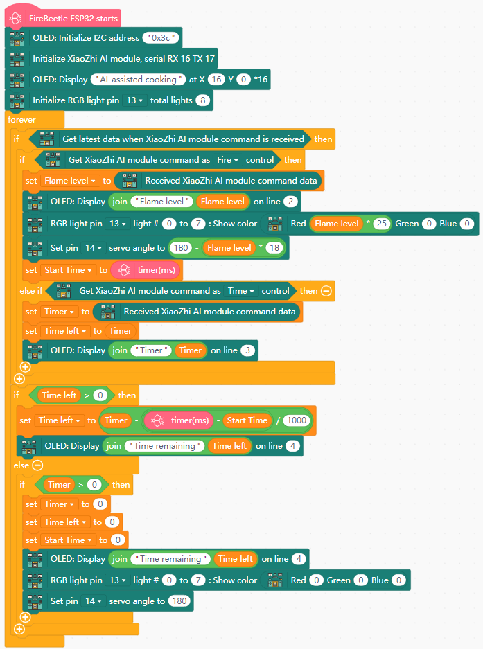
- AI-Assisted Cooking
- Create the variables
Timer,Time left,Start time, andFlame level. - Initialize the LED light ring on pin 13 with 8 lights.
- Initialize the OLED with I2C address 0x3c and display the text "AI-assisted cooking" on line 1.
- In forever:
- Get the lastest data from the AI module.
- If the AI module issues a command for Fire:
- Store the command data in
Flame level. - Display "Flame level:" and
Flame levelon OLED line 2. - Set the Red value of the LED light ring (pin 13) to
Instruction data* 25. - Set the servo angle (pin 14) to (180 - (
Instruction data* 18)). - Set
Start timeto the timer value (ms).
- Store the command data in
- Else if If the AI module issues a command for Time:
- Store the command data in
Timer. - Set the value of
Time lefttoTimer. - Display "Timer:" and
Timeron OLED line 3.
- Store the command data in
- If
Time left> 0:- Set
Time leftto (Timer- ((timer (ms) -Start time)/1000)). - Display "Time remaining:" and
Time lefton OLED line 4.
- Set
- Else if
Timer> 0:- Set
Timer,Start time, andTime leftto 0. - Turn off the LED light ring.
- Set servo angle to 180.
- Set
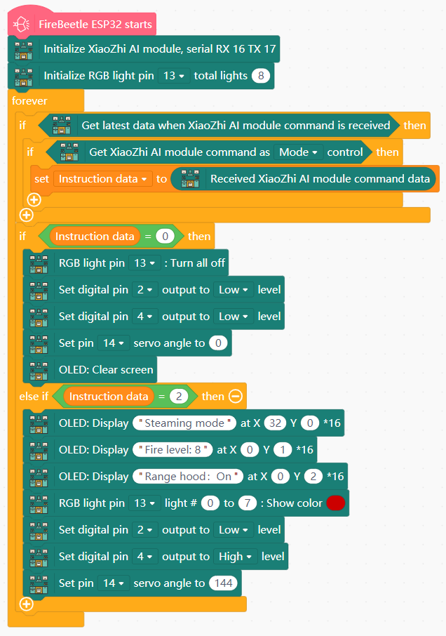
- AI Mode Switching
- Create the variable
Instruction data. - Initialize the OLED and LED light ring as before.
- In forever:
- Get the lastest data from the AI module.
- If the AI module issues a command for Mode, store the command data in
Instruction data. - If
Instruction data= 0:- Turn off the LED light ring (pin 13).
- Turn off the fan module (set pins 2 and 4 to Low).
- Set servo angle (pin 14) to 0.
- Clear the OLED screen.
- Else if
Instruction data= 2:- Display "Steaming mode" on OLED line 1.
- Display "Fire level: 8" on OLED line 2.
- Display "Range hood: On" on OLED line 3.
- Set the LED light ring to Red.
- Turn on the fan (set pin 2 to Low and pin 4 to High).
- Set servo angle to 144.
View Sample Program
View Sample Program
View Sample Program
Goal
Combine all prior projects into a single unified system.
Harware and Wiring
All devices and pins - refer to previous projects
- What are some problems you may have encountered during this project? How did you go about trying to solve them?
- For example, did all the text fit on the OLED screen as intended? If not, why did it struggle? What are some possible solutions to this? Are there any alternatives to using the OLED screen, or can the text be condensed to some extent?
- What are some additional features that could be added to the Smart Kitchen? Are there any additional capabilities that can be implemented using the hardware currently in place? Try it own by making your own programs.