Getting Started
Software: Mind+ (Upload Mode), Arduino C.
Key Concept: Using logic to transform a physical structure like a school campus into an intelligent system that enhances the life and learning of students and faculty.
Software & Drivers
Before building, ensure your environment is ready:
- Install Mind+: Download from the official website. Switch to "Upload Mode".
- Select Board: Choose "Arduino Uno" (or the specific controller board provided).
- Add Library: Go to Extensions > User Library > Import the "Smart Campus" or "Smart School" file.
- Install Drivers: Connect via USB. If the COM port is not found, click "Install Serial Driver" in Mind+.
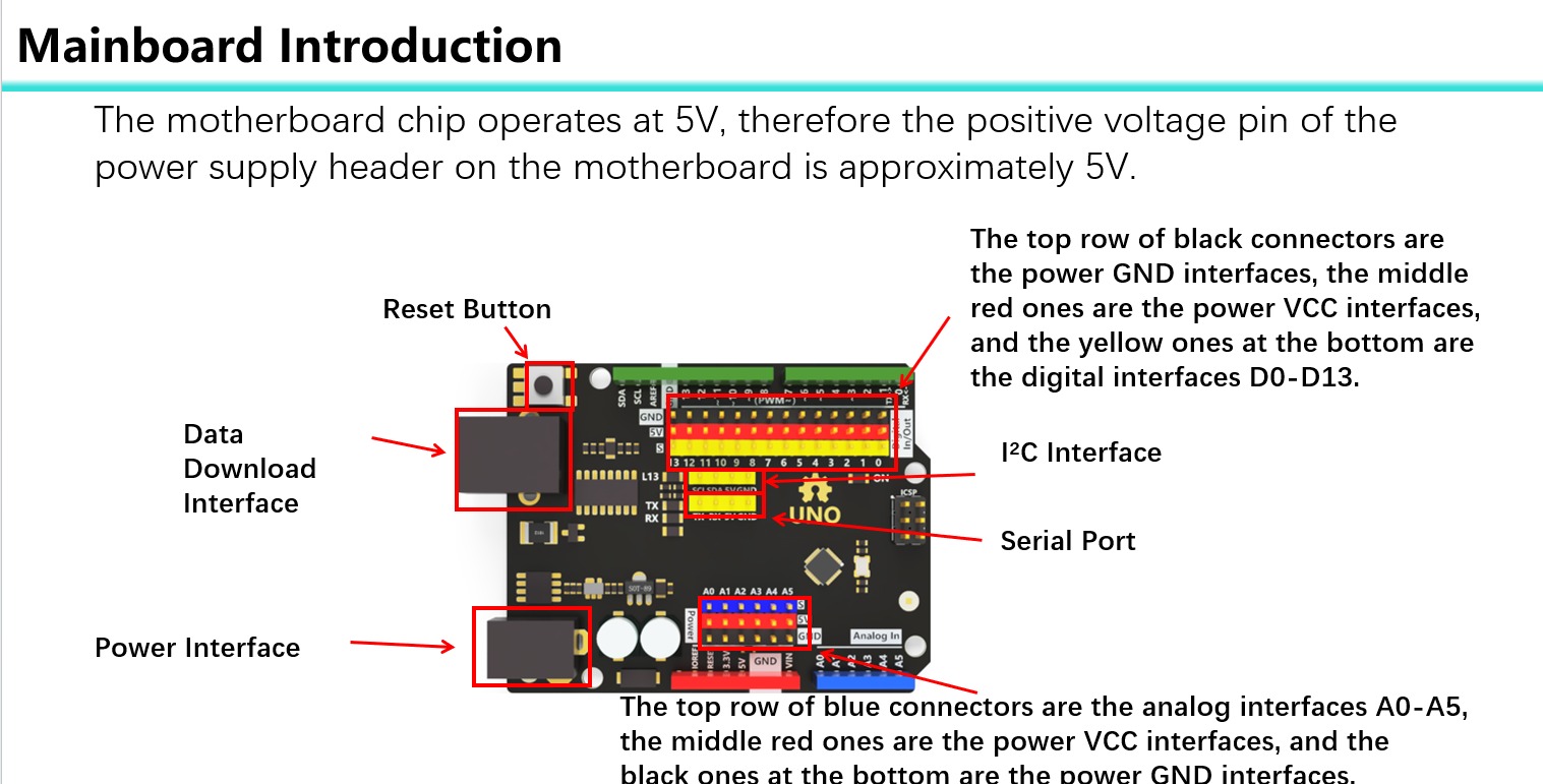
Hardware Basics
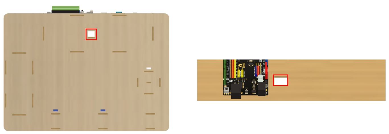
This project uses the Arduino Uno control board, which connects to a plethora of auxiliary devices to perform various actions. The specifics of the Arduino Uno are as follows:
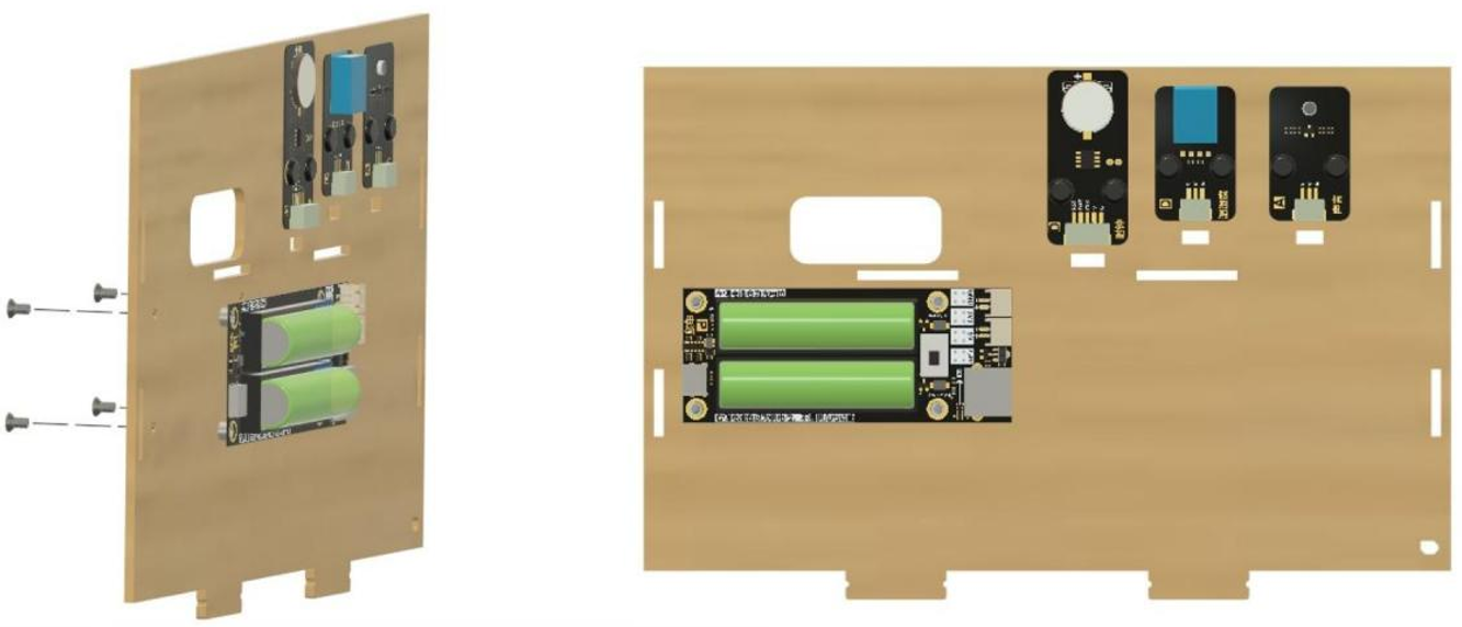
The project also includes a battery pack and charger as shown:
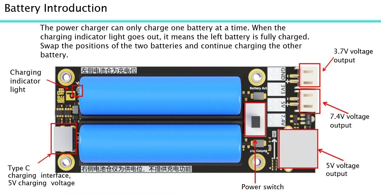
The power supply can only charge one battery at a time. When the charging indicator light goes out, it means the left battery is fully charged. Swap the positions of the two batteries and continue charging the other battery.
When using the mainboard motor drive, this power supply is required, and a 3.7V output is sufficient. Unplug the power cord when not in use.
Structural Assembly
The main structure consists of a number of wooden components and auxiliary devices. Below are the steps on how to properly assemble them into the Smart Campus model:
View Assembly Instructions
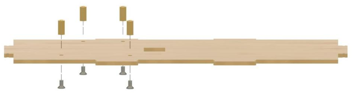
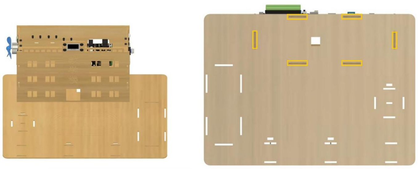
Main Building
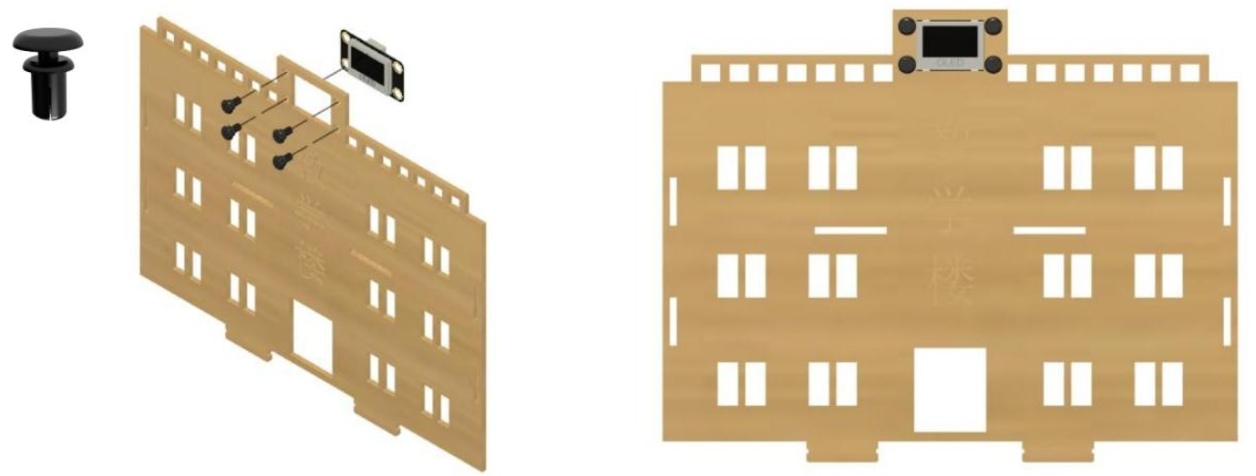
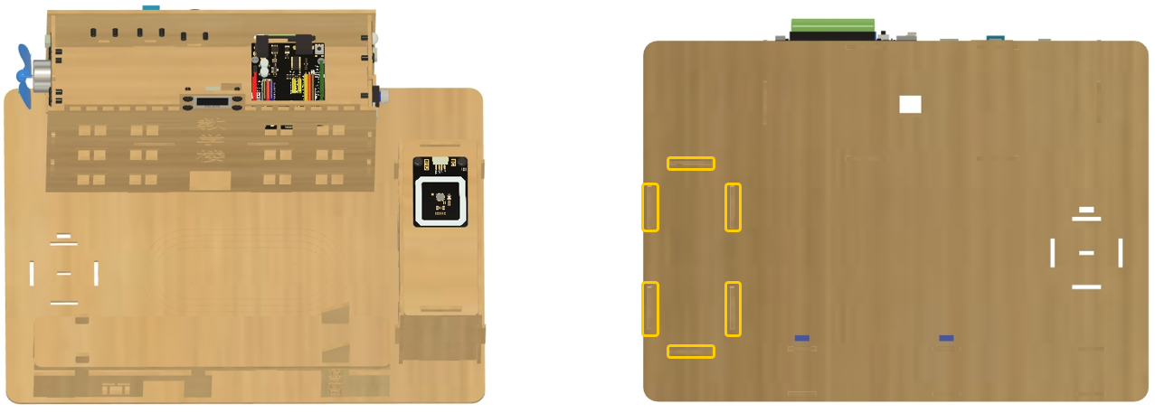
Take wooden plate #5 and screw four M3*6 countersunk screws through the screw holes and into the copper pillars. Pay attention to the orientation shown in the diagram.
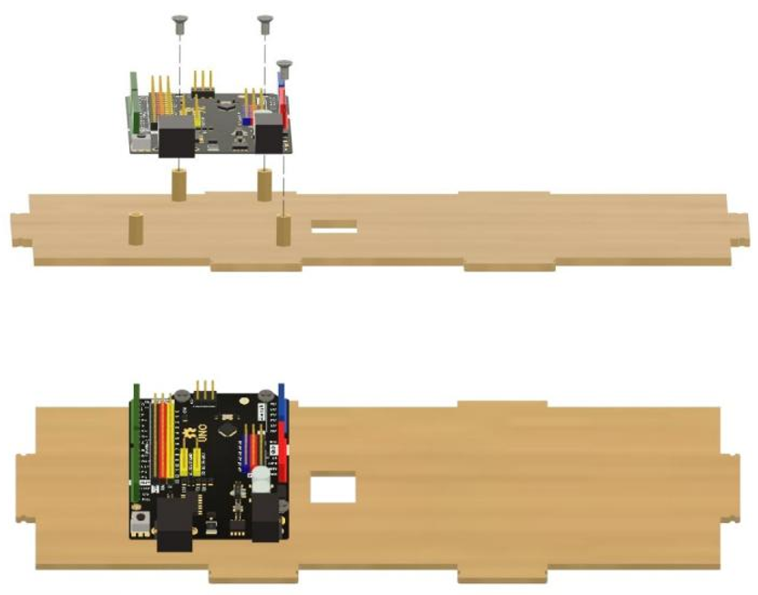
Using 3 more M3*6 countersunk screws, attach the Arduino Uno to the copper pillars as shown.
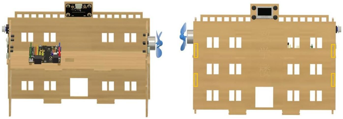
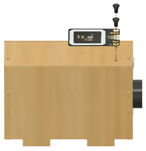
Attach the OLED screen to the space at the top of the wooden plate #2 using four of the black fasteners shown in the image. (Do not separate the two parts of the black fasteners, simply push them through the holes as indicated in the diagram until they tighten.)
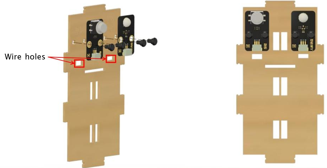
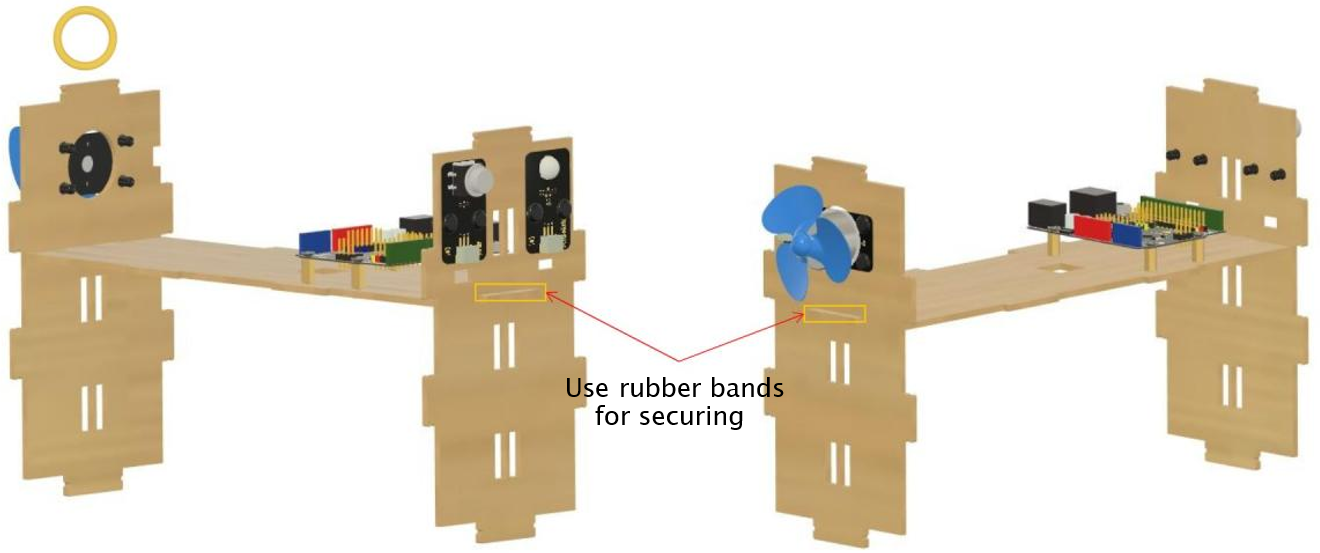
Take the right wall plate (wooden plate #3) and fasten the button and human sensor modules as shown.
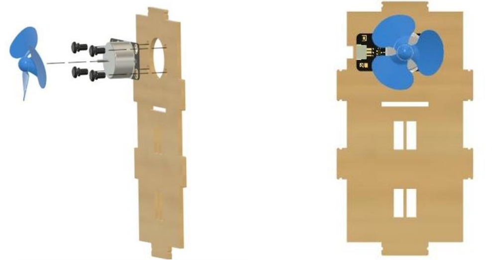
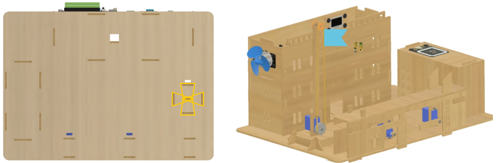
Take the left wall plate (wooden plate #4) and fasten the fan module in the position shown, then attach the fan head to the motor shaft.
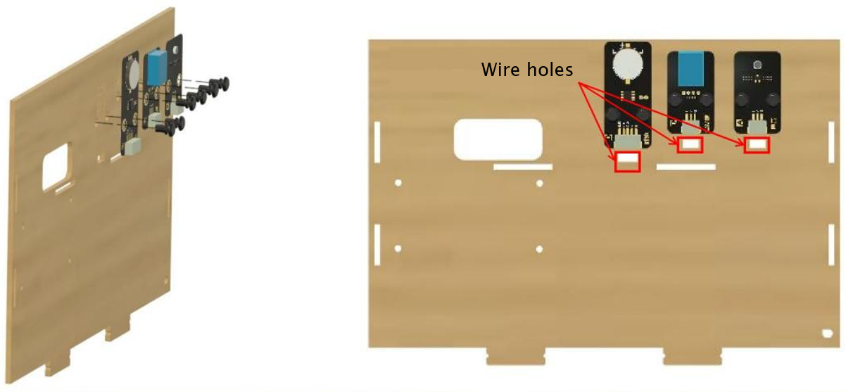
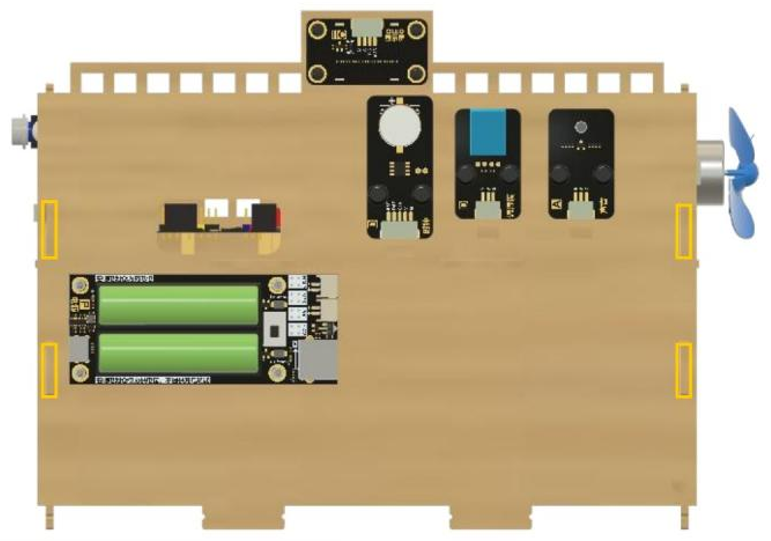
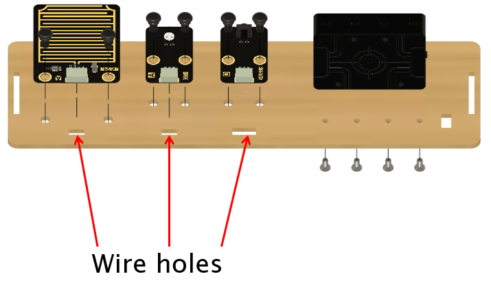
Take the back wall plate (wooden plate #6) and fasten (from left to right) the clock module, temperature and humidity sensor module, and the sound receiver module. Note the different widths of wire holes to account for different sized wire bundles (5-wire, 4-wire, etc.)
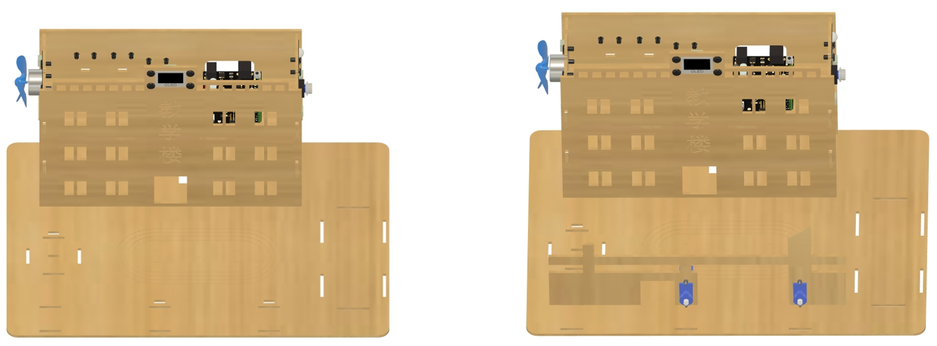
Connect the wall plates with the middle floor plate as depicted, and use the small rubber bands to secure the wooden tabs in place.
Connect this assembly to the two-part base plate (wooden plate #1) in the orientation depicted, again using rubber bands to hold the wooden tabs on the bottom of the structure.
School Gate
Take the school gate backboard (wooden plate #20) and attach the two 180-degree servo motors in the positions shown, fastening them to the board with a pair of long M2 screws and nuts. (Note: take care to use the 180-degree servos and not the 360-degree servo - despite their similar appearance, they are labeled accordingly on their bags.)
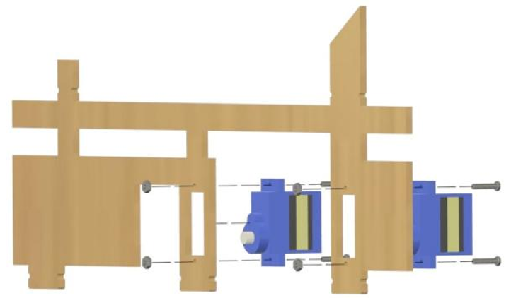
Affix the plastic servo arms to the servo heads in the positions shown, and then attach the wooden barrier arms (wooden plates #22 and #23) using the servos’ shaft screws.
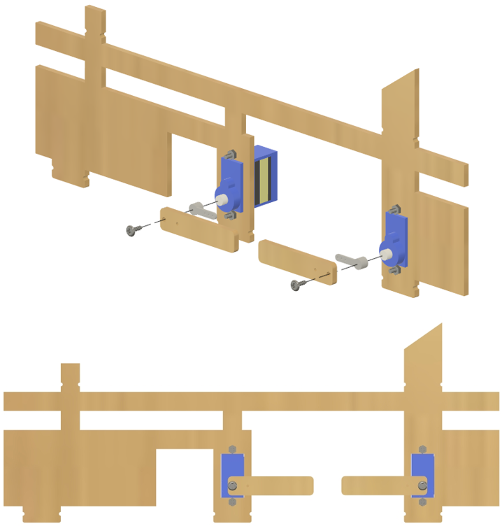
Affix the gate assembly to the base plate #1 in the position shown, and connect the gate front plate and roof plate (wooden plates #19 and #21, respectively), fastening the whole gate assembly together with rubber bands on the wooden tabs.
Canteen
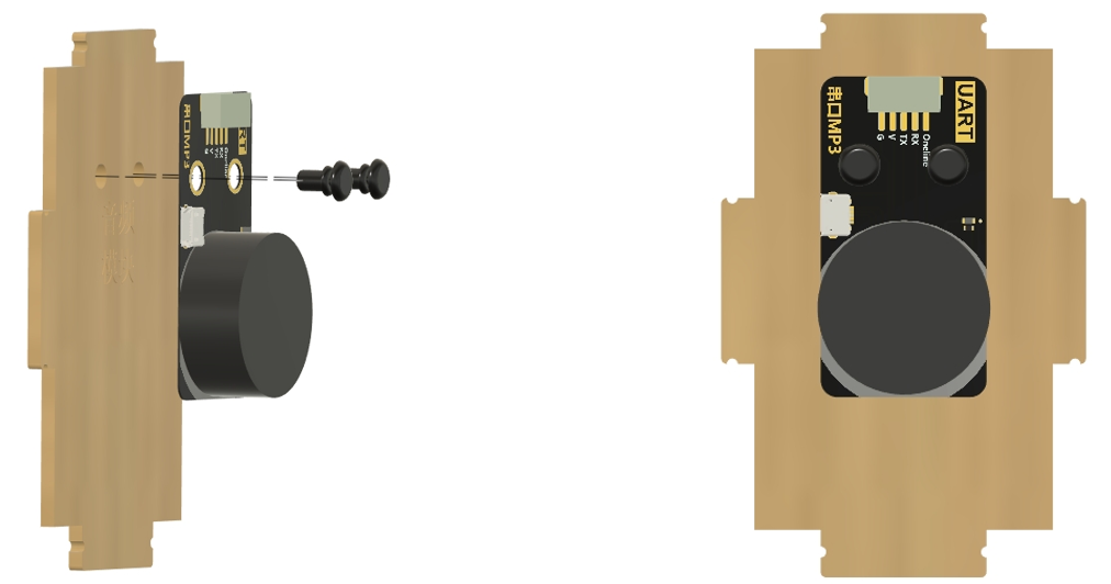
Take the left canteen wall plate (wooden plate #9) and fasten the MP3 module to it as shown.
Assemble the left canteen wall plate together with the right canteen wall plate (#10), the canteen front plate (#8), and the canteen back plate (#11) to complete the canteen structure, and fasten the wooden tabs with rubber bands.
Attach the RFID module to the canteen roof plate (wooden plate #12) as shown, then attach the canteen roof plate to the top of the canteen structure with the RFID module closer to the left wall and secure the wooden tabs with rubber bands.
Attach canteen building to platform base in the orientation shown, with the back wall facing the outside of the campus area, and secure the wooden tabs on the bottom of the base plate with rubber bands.
Flagpole
Assemble the flag platform base with wooden plates #13, #14, #15, #16, and #18 as shown in the diagram.
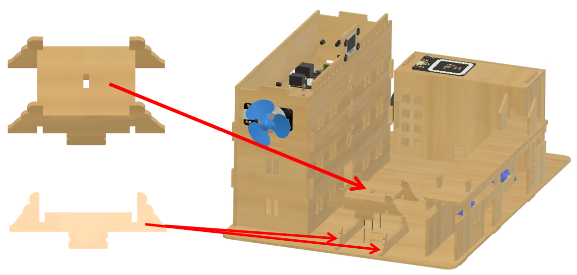
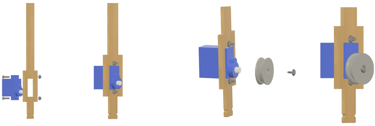
Take the flagpole (wooden plate #17) and insert the 360-degree servo through the rectangular hole, securing it with two M2 screws + nuts. Fix the large pulley wheel to the servo shaft using the servo shaft screw, then connect the small pulleys to the other end of the flagpole and run the large rubber band between the small and large pulleys.
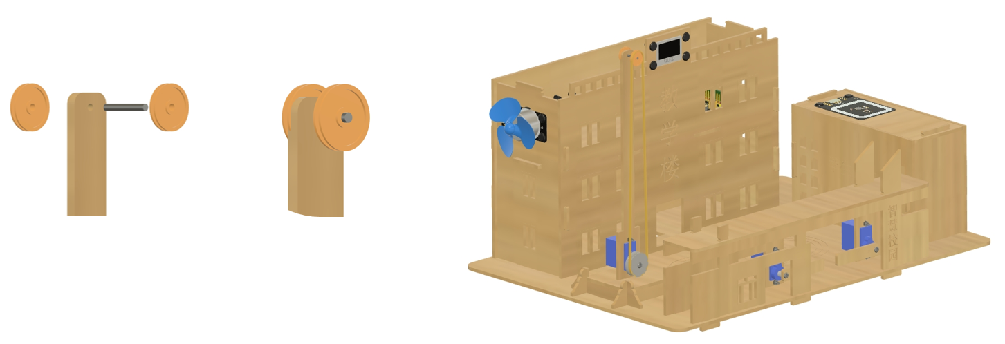
Insert the flagpole into the slot in the flagpole base, attach the flag to the rubber band at the top of the flagpole, and use four rubber bands to stabilize the structure underneath the base plate, as shown in the diagram.
Note that the 360-degree servo cable should be routed through the hole in the bottom of the main structure to reach the Arduino.
Front Sensors and RGB
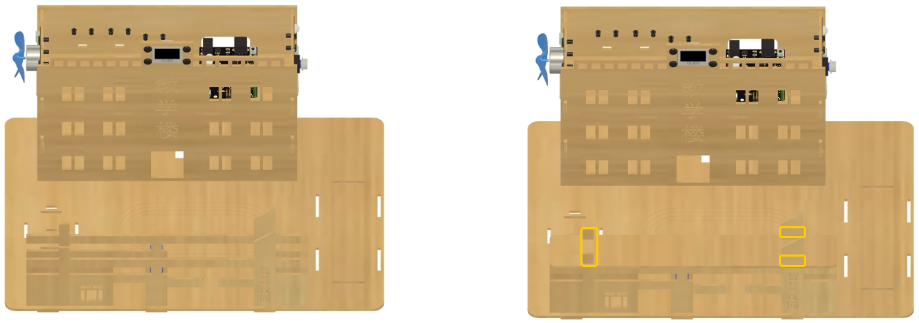
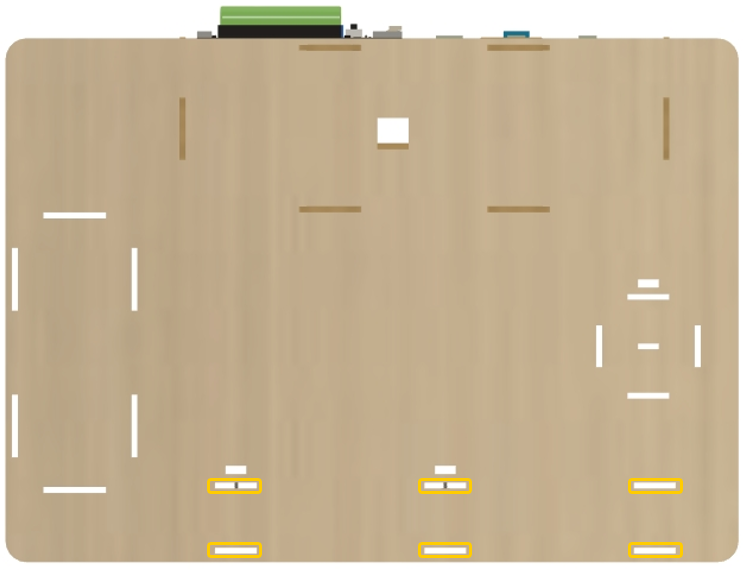
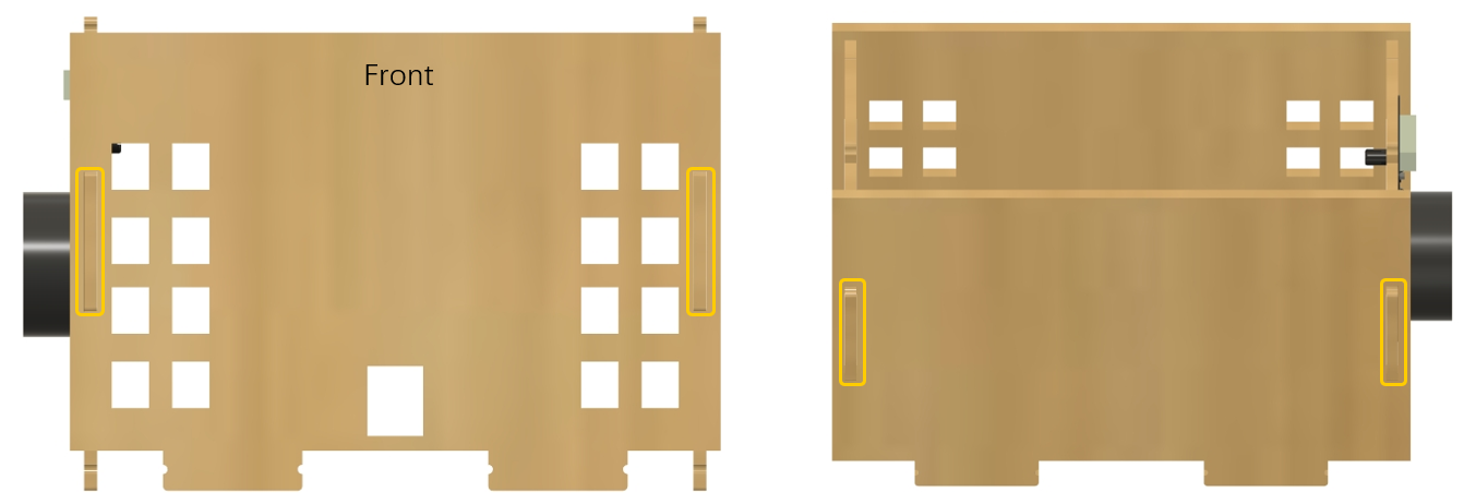
Attach the RGB light strip to the inside of the main building’s front wall.
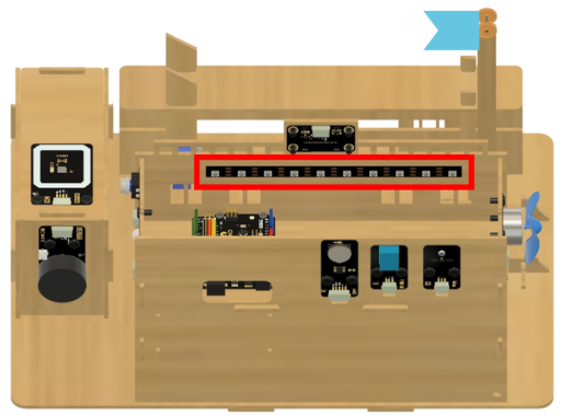
Fix the rain sensor, light sensor, IR receiver, and AI OLED screen modules to the main building roof plate (wooden plate #7) as shown; with their cables routed through the designated holes.
Attach the roof plate to the top of the main building and secure it in place with rubber bands.
Path A: Smart Lighting and Ambience
Using lights, displays, and sounds to communicate system status to the user.
Goals
- Light up a 10‑LED RGB strip with different colors using Mind+ blocks.
- Understand:
- LED numbers start from 0.
- Colors come from mixing Red, Green, Blue (each 0–255).
Hardware and Wiring
- RGB LED strip (10 LEDs):
- GND (black) → main board GND
- V / 5V (red) → main board 5V
- S / DIN (yellow) → main board D3
- Make sure the arrows on the strip point from the first LED toward the rest.
What You Do In Mind+
- Select board Arduino Uno in Mind+.
- In Extensions, add the Smart Campus library.
- In the main blocks, drag out the block “Uno starts” if it has not been added already.
- Under it, use a block to initialize the RGB light strip with pin 3 and 10 lights.
- In forever:
- Add a block: “RGB light pin [3] number [0] to [9] display color (…)”.
- Use the color picker or set R, G, B numbers to choose a color (e.g. red, green, blue).
- Click Upload to device and watch all LEDs light up with that color.
- To make segments: Add several “set LED range … to color …” blocks in the loop, for example:
- 0-1: red
- 2-3: yellow
- 4-5: green
- 6-7: blue
- 8-9: purple
View Sample Program
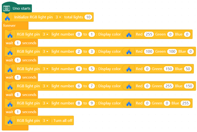
- At the very beginning, the board runs the “initialize RGB strip (pin 3, 10 LEDs)” block once. You can think of it as:
- “Dear board, there is a strip on pin 3, and it has 10 lamps to control.”
- Then the board keeps running the “repeat forever” part again and again. It is like it is constantly asking itself:
- “Which LED numbers should be turned on now, and what color should they be?”
- The LED numbers start from 0:
- The first LED is number 0.
- The second LED is number 1.
- ... the last LED is number 9.
- A color is made by three brightness values:
- Red (R), Green (G), Blue (B), each from 0 to 255.
- 0 means this color is off, 255 means this color is fully on.
- For example:
- (255, 0, 0) → only red is on → looks red.
- (0, 255, 0) → only green is on → looks green.
- (0, 0, 255) → only blue is on → looks blue.
- (255, 255, 255) → red, green and blue are all bright → looks almost white.
- When you choose different ranges (like 0–1, 2–3, 4–5…) and give each range a different color, you are basically telling the board:
- “LEDs 0–1: please be red; LEDs 2–3: please be yellow; ...”
Goals
- Use a light sensor to automatically turn a lamp/LED on when it is dark, and off when it is bright.
- Notice that:
- The light sensor produces a number that reflects brightness.
- The program compares this number with a “boundary” value.
Hardware and Wiring
- Light sensor:
- AO → A0
- V → 5V
- G → GND
- LED light strip:
- S → D3
- V → 5V
- G → GND
What You Do In Mind+
- Initialize the RGB light strip with pin 3 and 10 lights.
- In forever:
- Condition: if [light value] is smaller than a certain number (like 300).
- In the IF part: set light strip (pin 3) to ON / HIGH.
- In the ELSE part: set light strip to OFF / LOW.
- Upload and test by covering / uncovering the light sensor.
View Sample Program
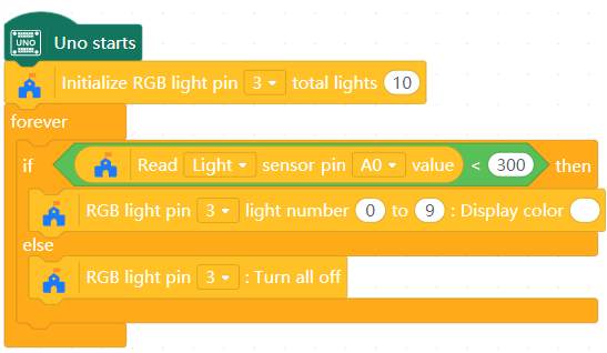
- The light sensor turns brightness into a number. When it is bright, the number is in one range; when it is dark, the number moves into another range.
- The program keeps doing the same thing again and again:
- “Read the light number.”
- “Compare it with my chosen boundary number (the threshold).”
- “If the light number means ‘dark’, turn the lamp on. If it means ‘bright’, turn the lamp off.”
- In short, this program follows the pattern:
- sensor value → compare with threshold → different actions.
Goals
- Make an LED/lamp slowly become brighter and then dimmer, like “breathing”.
- Observe that:
- Brightness can change step by step with a number.
- Repeating a small change many times creates a smooth effect.
Hardware and Wiring
- RGB light strip:
- S → D3
- V → 5V
- G → GND
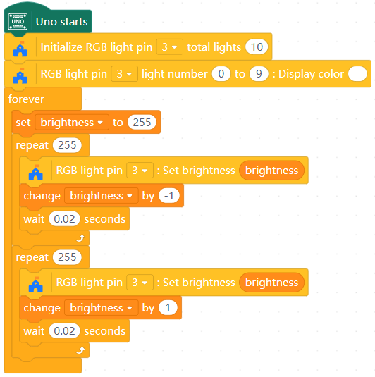
What You Do In Mind+
- Create the variable
brightness. - Initialize the RGB light strip with pin 3 and 10 lights, and use a block to have it display an initial color (e.g. white).
- In forever:
- Set
brightnessto 255. - Create a loop that repeats 255 times.
- Use a block that sets the output of pin 3 according to the value of
brightness(0–255). - Change
brightnessby -1. - Wait a short time (e.g. 20–30 ms).
- Create a second loop that repeats 255 times.
- Include the same blocks as the previous loop, but this time change
brightnessby 1.
- Set
View Sample Program
- The program remembers one number: how bright the lamp should be right now.
- Every short step it does:
- “Set the lamp to this brightness.”
- “Wait a tiny moment.”
- “Make the brightness number a bit larger or smaller.”
- When the brightness number reaches the top or bottom, the program turns around:
- It starts decreasing instead of increasing, or vice versa.
- By repeating this simple change many times, the human eye sees a smooth breathing effect.
- The same idea later can control fan speed: “blowing stronger”, “blowing weaker” with the same pattern.
Goals
- Let a button start and stop a running light effect on the RGB strip.
- Observe that:
- The button gives a simple on/off signal.
- The program “remembers” whether it is in running mode or stopped mode.
Hardware and Wiring
- RGB light strip:
- S → D3
- V → 5V
- G → GND
- Button module:
- S → D4
- V → 5V
- G → GND
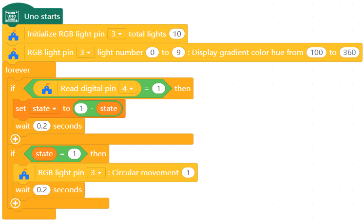
What You Do In Mind+
- Create the variable
state. - Initialize the RGB light strip with pin 3 and 10 lights.
- In forever:
- Read the button state (pressed or not) by getting the value from pin 4.
- If the value is 1 (i.e. the button is pressed):
- Invert
stateby setting it to 1 -state. - Wait for 0.2 seconds.
- Invert
- In a separate IF statement, if
stateis equal to 1:- Add a block to activate the “circular movement” on the RGB light strip at pin 3 with value 1.
- Wait for 0.2 seconds.
View Sample Program
- The button is like a remote control with only one key. The program uses it to switch between two modes:
- Mode 0: stop (no running light).
- Mode 1: run (turn on LEDs one by one).
- Each time the button is pressed, the program flips its memory:
- “I was stopped, now I start running.”
- Or: “I was running, now I should stop.”
- When in running mode, the program:
- Lights one LED, moves the lit LED to the next position, and repeats.
- This illustrates a very important pattern:
use a variable to remember the current modeinstead of only reacting directly to the button.
Path B: Smart Fans & Environmental Comfort
Implementing sensor-based "Watchdogs" to prevent accidents.
Goals
- Turn the fan on and off.
- Use different “gears” (low/medium/high) by changing the fan’s strength.
- Show that:
- The fan speed can be controlled by a number (0–255), similar to lamp brightness.
Hardware and Wiring
- Fan module
- S → D6
- V → 5V
- G → GND
- Button module:
- S → D4
- V → 5V
- G → GND
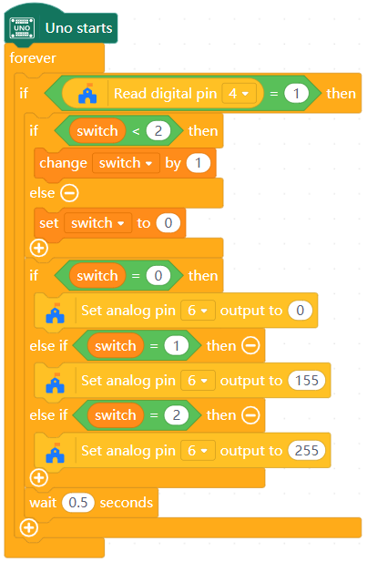
What You Do In Mind+
- Ensure that the fan module is selected in Extensions.
- Create the variable
switch. - In forever:
- Read the button state (pressed or not) by getting the value from pin 4.
- If the value is 1 (i.e. the button is pressed):
- If
switch< 2, increaseswitchby 1. - Else if
switch= 2, setswitchto 0
- If
- Use another IF block to decide fan output based on switch:
- switch 0 → fan OFF (strength 0).
- switch 1 → fan strength 155.
- switch 2 → fan strength 255 (maximum).
- Wait 0.5 seconds.
View Sample Program
- The fan is just like the lamp in the breathing-light lesson: it understands “how strong” it should run as a number between 0 and 255.
- 0 means no power → fan stops. Bigger numbers mean more power → stronger wind.
- By connecting the fan’s strength to a small number of “gears”, we understand:
One variable can represent a mode(gear), and each mode maps to a different output level.
Goals
- Automatically adjust fan speed based on temperature.
- Show that:
- Sensor → number (temperature).
- Number → choose fan speed using rules.
Hardware and Wiring
- Fan module
- S → D6
- V → 5V
- G → GND
- Temperature/humidity sensor:
- S → D5
- V → 5V
- G → GND
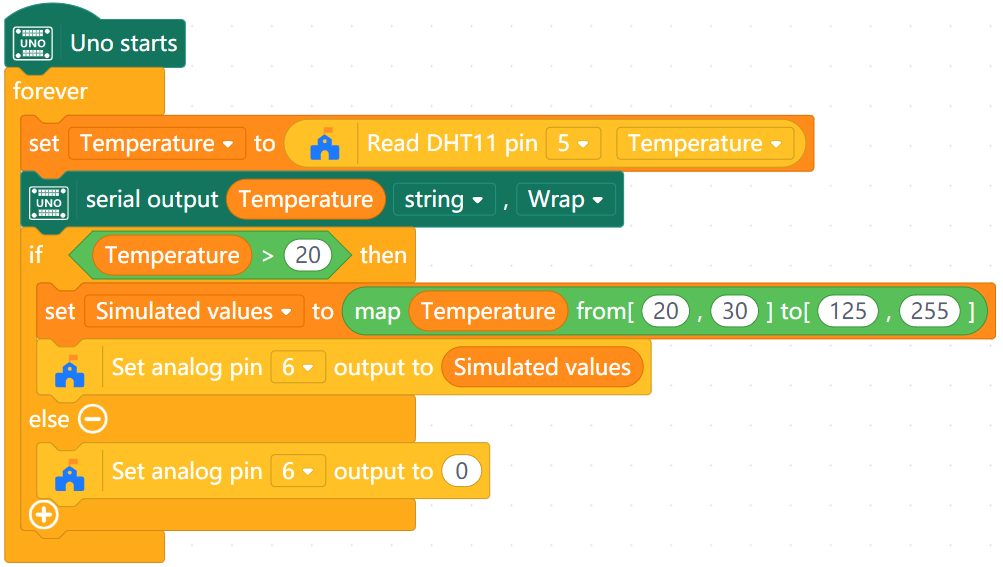
What You Do In Mind+
- Create the variables
temperatureandSimulated values. - In forever:
- Read value from temperature sensor (pin 5) into the
temperaturevariable.- (Optional) Display
temperatureon OLED or serial output to understand typical values.
- (Optional) Display
- If Temperature < 20°C → fan OFF.
- If Temperature > 20°C:
- Map the temperature range from 20-30 to fan strength 155-255, and store it in the
Simulated valuesvariable. - Set fan value (pin 6) to
Simulated values.
- Map the temperature range from 20-30 to fan strength 155-255, and store it in the
- Read value from temperature sensor (pin 5) into the
View Sample Program
- The temperature sensor turns “how hot the classroom is” into a number.
- The program uses a simple “temperature to fan gear” table:
- Cool → fan off.
- A little warm → small wind.
- Hot → strong wind.
- This is again the pattern:
- sensor number → compare with several boundaries → choose a mode (fan speed).
Goals
- Use an IR remote to:
- Turn fan on/off.
- Switch fan gears (low/medium/high).
- Optionally fine-tune speed up/down.
- Show that:
- Remote buttons are just codes; program decides what each code means.
Hardware and Wiring
- Fan module
- S → D6
- V → 5V
- G → GND
- IR receiver:
- S → D2
- V → 5V
- G → GND
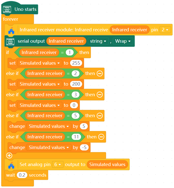
What You Do In Mind+
- Create the variables
Infrared receiverandSimulated values. - In forever:
- Read the IR signal from pin 2 into
Infrared receiver.- (Optional) Display
Infrared receiveron OLED or serial output to understand typical values.
- (Optional) Display
- When a certain IR code is received:
- Key “1” code → set
Simulated valuesto 255. - Key “2” code → set
Simulated valuesto 200. - Key “3” code → set
Simulated valuesto 0. - Keys “5” and “11” → change
Simulated valuesby 5 or -5, respectively.
- Key “1” code → set
- After handling IR input, set the fan output (analog pin 6) to the value of
Simulated values.
- Read the IR signal from pin 2 into
View Sample Program
- The IR remote is like a keyboard in the air. Each key sends a different code.
- The program “translates” codes into actions:
- “If I see code X, that means user wants high speed.”
- “If I see code Y, that means user wants off.”
- “If I see code Z, that means user wants a little faster.”
- This shows a general rule:
- Inputs from different devices (buttons, remotes) can all be turned into changes of the same state variable (fan gear or speed).
Path C: Motorized Devices - Flags and Gates
Use abd control of servo motors and servo-driven devices.
Goals
- Use a 360° servo to pull the belt and raise/lower the flag.
- Use button control to:
- Raise the flag.
- Lower the flag.
- Stop at top/bottom positions (by timing).
Hardware and Wiring
- 360° servo at flagpole:
- S → D13
- V → 5V
- G → GND
- Button module:
- S → D4
- V → 5V
- G → GND
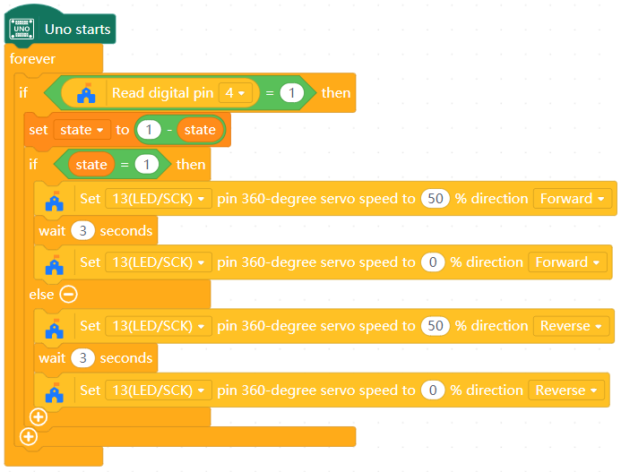
What You Do In Mind+
- Create the variable
state. - In forever:
- Create a simple test:
- Rotate servo in one direction for a short time (flag goes up or down).
- Rotate in the other direction (flag moves opposite way).
- From there, design:
- A “raise” sequence: rotate forward at 50% for 3 seconds, then stop.
- A “lower” sequence: rotate in reverse at 50% for 3 seconds, then stop.
- Use a button to trigger one of these sequences by changing
state:- Press button → invert the value of
state. - Run the “raise” sequence if
state= 1. - Run the “lower” sequence if
state= 0.
- Press button → invert the value of
- Create a simple test:
View Sample Program
- The 360° servo does not know its angle; it only knows “turn one way” or “turn the other way” at some speed.
- The program uses time to guess how far the flag has moved:
- “If I turn for 3 seconds, that should be enough to move from bottom to top.”
- This shows that:
- Sometimes we use time as an approximate control when we cannot measure exact position.
Goals
- Use IR remote keys to:
- Fine-adjust flag up/down manually.
- Start a full “raise to top” or “lower to bottom” action automatically.
- Prevent raising when the flag is already at the top, and prevent lowering when at the bottom.
Hardware and Wiring
- 360° servo at flagpole:
- S → D13
- V → 5V
- G → GND
- IR receiver:
- S → D2
- V → 5V
- G → GND
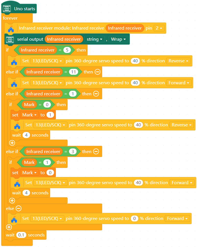
What You Do In Mind+
- Create the variables
Infrared receiverandMark. - In forever:
- Read the IR receiver value (pin 13) into
Infrared receiver. - Assign IR keys:
- Key 5 to manually raise the flag.
- Key 11 to manually lower the flag.
- Key 1 to raise the flag fully.
- Key 3 to lower the flag fully.
- When receiving the “5” key, raise the flag (rotate forward).
- When receiving the “11” key, lower the flag (rotate reverse).
- When receiving the “1” key and
Mark> = 0:- Run the raising sequence (rotate forward for 4 seconds).
- Set
Mark= 1.
- When receiving the “3” key and
Mark= 1:- Run the lowering sequence (rotate reverse for 4 seconds).
- Set
Mark= 0.
- When no actions are happening, set the rotation speed to 0 (this allows the actions of keys 5 and 11 to be stopped).
- Read the IR receiver value (pin 13) into
View Sample Program
- The AI board does not actually “see” the flag position; instead, it trusts that:
- “If I start from bottom and run my raise sequence once, I reach top.”
- The
Markvariable is the program’s memory of where the flag should be now. - By checking
Markbefore moving, we avoid “over-raising” or “over-lowering” the flag.
Goals
- Use the clock module to automatically:
- Lower the flag at a fixed time (for example 7:55).
- Raise the flag for the ceremony at another time (for example 8:00).
- Make sure each action happens only once per day.
Hardware and Wiring
- 360° servo:
- S → D13
- V → 5V
- G → GND
- DS1302 clock module:
- RST → D7
- DAT → D8
- CLK → D9
- V → 5V
- G → GND
- OLED:
- SCL → SCL
- SDA → SDA
- V → 5V
- G → GND
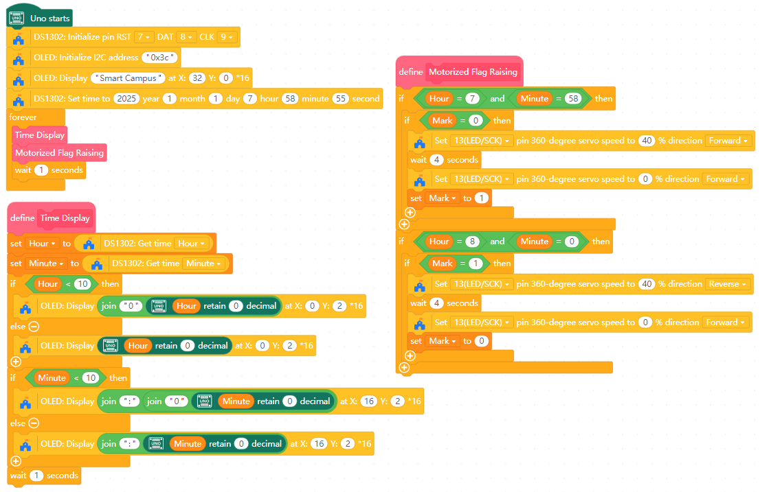
What You Do In Mind+
- Add the OLED and Clock extensions in Mind+.
- Initialize the OLED with address 0x3c.
- Initialize the DS1302 clock module with RST/DAT/CLK on pins 7/8/9.
- Optional: Set the OLED screen to display the text “Smart Campus”.
- Set the clock module time to the current date and
- Create the variables
Hour,Minute, andMark. - Create a function named Time Display that does the following:
- Read hour and minute from clock module into
HourandMinute. - Use blocks to display the values for
HourandMinuteon the OLED screen.- Optional: Use a series of IF statements and conditions to append a 0 to
HourorMinuteif their values are below 10, to reflect real clock formatting.
- Optional: Use a series of IF statements and conditions to append a 0 to
- Read hour and minute from clock module into
- Create a function named Motorized Flag Raising that does the following:
- If time is 7:55 and
Mark= 0:- Run raising sequence for the flag.
- Set
Mark= 1.
- If time is 8:00 and
Mark= 1:- Run lowering sequence for the flag.
- Set
Mark= 0.
- If time is 7:55 and
- In forever:
- Add function calls for Time Disiplay and Motorized Flag Raising.
- Wait 1 second.
View Sample Program
- The board keeps checking the clock like a punctual assistant:
- “Is it 7:55 now? If yes, and I haven’t lowered the flag yet today, I must lower it.”
- “Is it 8:00 now? If yes, and I haven’t raised it yet today, I must raise it.”
- The
Markvariable prevents the board from repeating the same action many times during that minute. - This pattern “time + one-time flag” is also used later for the class bell.
Goals
- Control left/right barrier gates with IR remote.
- Count cars entering/leaving a parking area and show the number on OLED.
Hardware and Wiring
- IR receiver:
- S → D2
- V → 5V
- G → GND
- 180-Degree Servos:
- Left servo: S → D11
- Right servo: S → D12
- V → 5V
- G → GND
- OLED:
- SCL → SCL
- SDA → SDA
- V → 5V
- G → GND
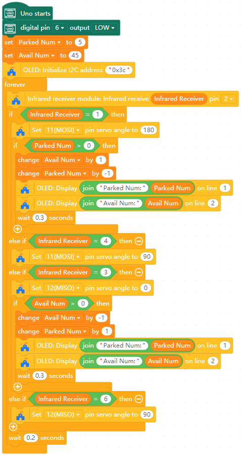
What You Do In Mind+
- Create the variables
Parked Num(initial value 5),Avail Num(initial value 45), andInfrared receiver. - Initialize two 180° servos (left and right) on digital pins 11 and 12.
- Initialize OLED screen.
- Determine the open and closed angles for each gate servo, and design sequences to open and close the gates.
- In forever:
- Read the IR receiver value (pin 2) into
Infrared receiver. - When a car "leaves" (
Infrared receiver= 1):- Open the exit gate (pin 11).
- Change
Avail Numby 1. - Change
Parked Numby -1. - Display updated Parked and Avail info on the OLED screen.
- Wait 0.3 seconds.
- When a car "enters" (
Infrared receiver= 3):- Open the entrance gate (pin 12).
- Change
Avail Numby -1. - Change
Parked Numby 1. - Display updated Parked and Avail info on the OLED screen.
- Wait 0.3 seconds.
- If
Infrared receiver= 4, close the exit gate. - If
Infrared receiver= 6, close the entrance gate. - Wait 0.2 seconds.
- Read the IR receiver value (pin 2) into
View Sample Program
- Each key on the remote means a high-level action:
- “Open left gate”, “Close left gate”, “Open right gate”, “Close right gate”.
- The system treats each gate event as:
- “One car in” (+1) or “one car out” (-1).
- The variable
Parked Numis a simple model of how many cars are inside. - From
Avail Num, it can also display how many spaces remain. - This pattern of counting + display can be re-used for:
- People in a room, books in a library shelf, shared bikes, etc.
Path D: Environment Monitoring & Safety Alerts
Using a variety of physical conditions based on surroundings to control or trigger different tasks.
Goals
- Use a sound sensor to measure noise and show the result on OLED.
- Understand that:
- Sound → sensor voltage → number.
- The number will jump when the environment becomes noisy.
Hardware and Wiring
- Sound sensor:
- AO → A1
- V → 5V
- G → GND
- OLED:
- SCL → SCL
- SDA → SDA
- V → 5V
- G → GND
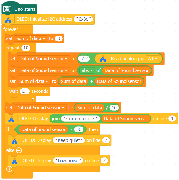
What You Do In Mind+
- Create the variables
Sound sensor dataandSum of data. - Initialize OLED screen.
- In forever:
- Read value from pin A1 into
Sound sensor data. - If the value does not reflect real sound values, use some calculations to adjust this value and store it in
Sum of data. - If adjusted, return this value into
Sound sensor data - Display
sound sensor dataon the OLED screen, along with a label such as "Noise:". - Add additional lines for if the volume crosses certain thresholds, such as "Keep quiet" or "Noise levels low".
- Read value from pin A1 into
View Sample Program
- The sound sensor gives a numeric hint of how strong the sound is at the moment.
- The program simply shows this number, letting students connect:
- “Quiet environment → small number.”
- “Clapping or shouting → large number.”
- This prepares for more advanced uses (like nap noise warning) later.
Goals
- Use a raindrop sensor to detect whether it is raining or not.
- Show raw sensor value and a simple Yes/No message on OLED.
Hardware and Wiring
- Raindrop sensor:
- AO → A2
- V → 5V
- G → GND
- OLED:
- SCL → SCL
- SDA → SDA
- V → 5V
- G → GND
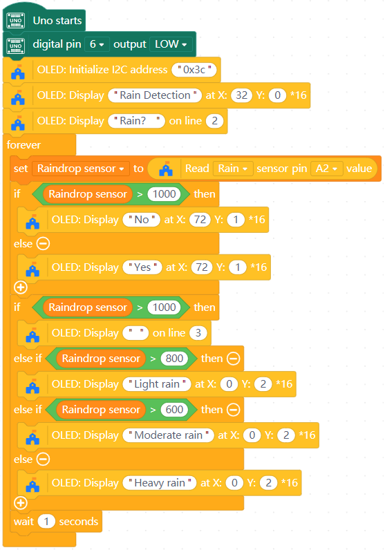
What You Do In Mind+
- Create the variable
Raindrop sensor. - Initialize OLED screen.
- Display "Rain Sensor" on OLED line 1 and "Rain?" on OLED line 2.
- In forever:
- Read value from pin A2 into
Raindrop sensor. - Display the rain level on the OLED based upon certain thresholds:
Raindrop sensor> 1000: display nothingRaindrop sensor> 800 → "Light rain"Raindrop sensor> 600 → "Moderate rain"- Else: → "Heavy rain"
- Notice that a higher
Raindrop sensorvalue corresponds to a lower amount of rainfall.
- Read value from pin A2 into
View Sample Program
- It transforms a raw analog value into an easy-to-understand judgement:
- “Yes, it’s raining.” or “No, it’s dry.”, and the amount it is raining.
- This Yes/No decision is also used as a trigger for voice reminders.
Goals
- Use the noise sensor to monitor classroom noise during noon nap time only.
- Use RGB strip color (green/yellow/red) to show the noise level.
- Observe that:
- Sensor value → multi-level warning (not just on/off).
- Program behavior can depend on time (only active at nap time).
Hardware and Wiring
- Sound sensor:
- AO → A1
- V → 5V
- G → GND
- RGB light strip:
- S → D3
- V → 5V
- G → GND
- Clock module:
- RST → D7
- DAT → D8
- CLK → D9
- V → 5V
- G → GND
- OLED:
- SCL → SCL
- SDA → SDA
- V → 5V
- G → GND
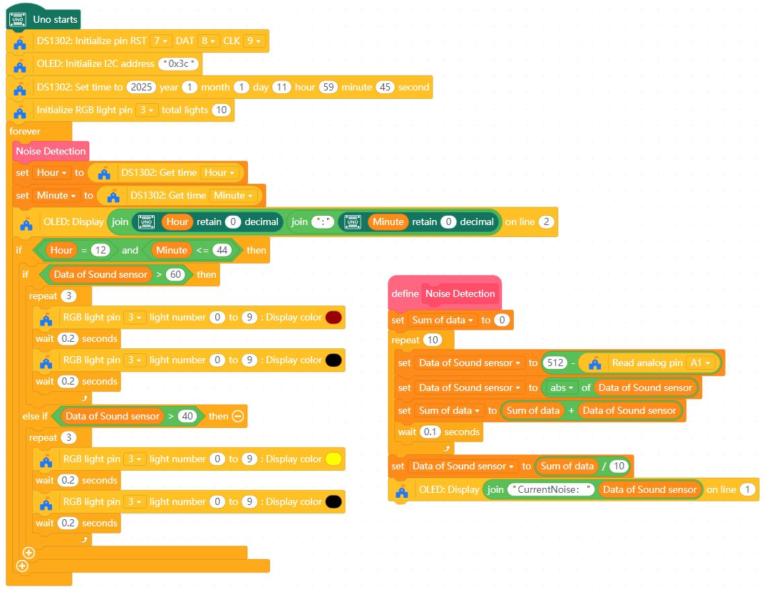
What You Do In Mind+
- Initialize the clock module, OLED screen, and RGB light strip.
- Set the clock module to a time convenient to the exercise.
- Create the variables
Sound sensor data,Sum of data,Hour, andMinute. - Create the function Noise Detection that does the following:
- Read the sound sensor value from A1 into
Sound sensor data. - Adjust the sound sensor value using calculations and
Sum of data, before reading it back intoSound sensor data. - Display "Current noise:" and
Sound sensor dataon OLED line 1.
- Read the sound sensor value from A1 into
- In forever:
- Call the Noise Detection function to give the value of
Sound sensor data. - Store the time value from the clock module in
HourandMinute. - Use an IF block to check if the current time is during nap time (e.g. 12:00-12:45). If it is:
- If
Sound sensor datais high (e.g. over 60), have the RGB light strip rapidly flash red. - If
Sound sensor datais medium (e.g. between 40 and 60), have the RGB light strip flash yellow. - If
Sound sensor datais low (e.g. under 40), have the RGB light strip shine green.
- If
- If it is not nap time, turn the light strip off.
- Call the Noise Detection function to give the value of
View Sample Program
- The noise sensor produces a number that moves up and down as the sound changes.
- Instead of only “quiet / noisy”, this program splits noise into several levels:
- Quiet → green.
- A bit noisy → yellow.
- Too loud → red.
- The program also checks the clock:
- If it is nap time, then we care about noise and show warnings.
- If it is not nap time, we ignore the noise or show no warning.
- So the final decision is based on two things together:
- Time period (nap or not) and noise level.
Goals
- Use a rain sensor to detect rain.
- Play voice messages to remind people to take umbrellas and walk carefully.
Hardware and Wiring
- Rain sensor:
- AO → A2
- V → 5V
- G → GND
- Audio module:
- RX → D1
- V → 5V
- G → GND
- OLED:
- SCL → SCL
- SDA → SDA
- V → 5V
- G → GND
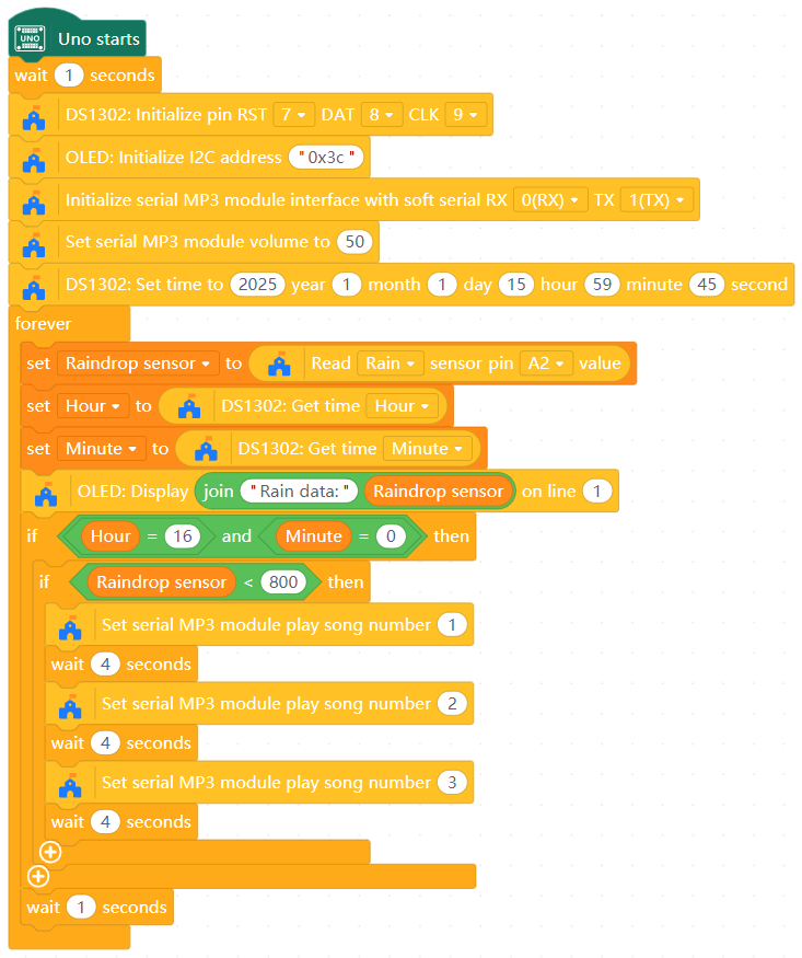
What You Do In Mind+
- Initialize the audio module and OLED screen.
- Set the clock module to a time convenient to the demonstration.
- Create the variable
Raindrop sensor. - In forever:
- Store the value from the rain sensor in
Raindrop sensor. - Display "Rain data:" and
Raindrop sensoron OLED line 1. - If
Raindrop sensoris below a certain value (e.g. 800):- Play a sound or series of sounds to indicate heavy rain.
- Optional: Incorporate the DS1302 clock module and additional variables to have the rain alarm only play if it is also a certain time of day.
- Store the value from the rain sensor in
View Sample Program
- First, turn the rain sensor value into a simple yes/no decision: “Is it raining now?”
- Then, decide whether to speak based on:
- Is it raining now?
- Has this reminder already been played recently?
- (Optionally) Is it dismissal time?
Goals
- Trigger an alarm when the PIR sensor detects motion.
- Show status on OLED, and allow a button to cancel the alarm.
- Teach the idea of:
- Event (motion) → start alarm.
- Another event (button) → stop alarm.
- Program must keep checking both while running.
Hardware and Wiring
- PIR motion sensor:
- S → D10
- V → 5V
- G → GND
- Audio module:
- RX → D1
- V → 5V
- G → GND
- Button module:
- S → D4
- V → 5V
- G → GND
- OLED:
- SCL → SCL
- SDA → SDA
- V → 5V
- G → GND
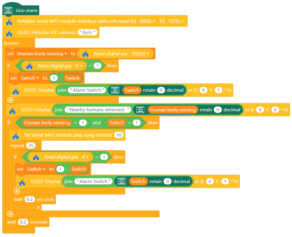
What You Do In Mind+
- Initialize the audio module and OLED screen.
- Create the variables
Human body sensingandSwitch. - In forever:
- Read the PIR sensor value into
Human body sensing. - Read the button state value into
Switch. - If
Human body sensing≥ 1 andSwitch= 0:- Set
Switchto 1. - Play an alarm sound on the audio module.
- Show a warning message (e.g. "Motion detected") on OLED screen, or display the number of people detected according to
Hman body sensing.
- Set
- If the cancel button is pressed and
Switch= 1:- Turn off the alarm.
- Set
Switch= 0. - Revert the OLED screen message to a default (e.g. "No motion").
- Keep this loop very short (no long “wait 5 seconds”), so that the program can quickly notice the button press. (0.2 seconds is likely sufficient)
- Read the PIR sensor value into
View Sample Program
- The PIR sensor only tells if there is motion now or not (1 or 0). It does not remember anything.
- The program uses
Switchto remember:- “I am currently in alarm state” or “I am in normal state”.
- When motion happens and alarm is off:
- The program switches into alarm mode: plays sound, shows warning.
- When the cancel button is pressed:
- The program switches back to normal mode: stops alarm, updates display.
- The key idea is that the loop keeps running quickly, so the board can respond to both the sensor and the button almost in real time.
Path E: Information Display & Time Management
Using digital modules to manage and display numerical and text data.
Goals
- Initialize OLED screen and show simple text.
- Understand:
- Screen has limited rows and columns.
- Some display blocks clear a line; some draw at a coordinate.
Hardware and Wiring
- Temperature/humidity sensor:
- S → D5
- V → 5V
- G → GND
- OLED:
- SCL → SCL
- SDA → SDA
- V → 5V
- G → GND
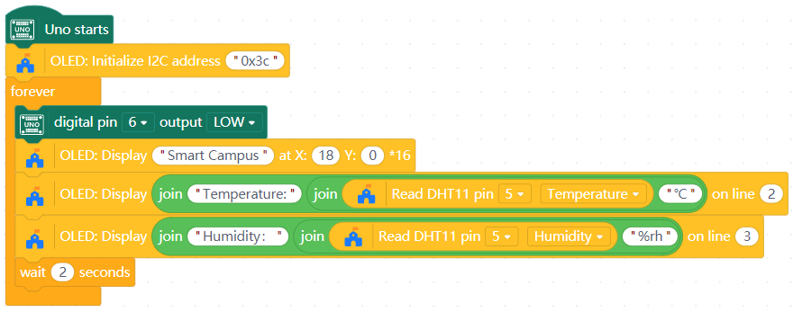
What You Do In Mind+
- Add OLED extension in Mind+.
- Initialize the OLED module at address 0x3c.
- In forever:
- Show a titled or welcome message, e.g. "Smart Campus", on OLED line 1.
- Show additional text on other lines.
- For example, have it display "Temperature:" and the temperature data from pin 5.
- You can also do this with humidity data.
View Sample Program
- The OLED is like a very small whiteboard:
- Each line can hold a limited number of characters.
- You often need to clear or overwrite old content.
- The program chooses:
- what information is important to show (title, sensor values, messages).
- where to place it on the screen.
- Other exercises use the OLED to show time, schedule, counts, etc.
Goals
- Use the clock module to read real time.
- Display hours and minutes (and optionally date) on OLED.
Hardware and Wiring
- DS1302 clock module:
- RST → D7
- DAT → D8
- CLK → D9
- V → 5V
- G → GND
- OLED:
- SCL → SCL
- SDA → SDA
- V → 5V
- G → GND
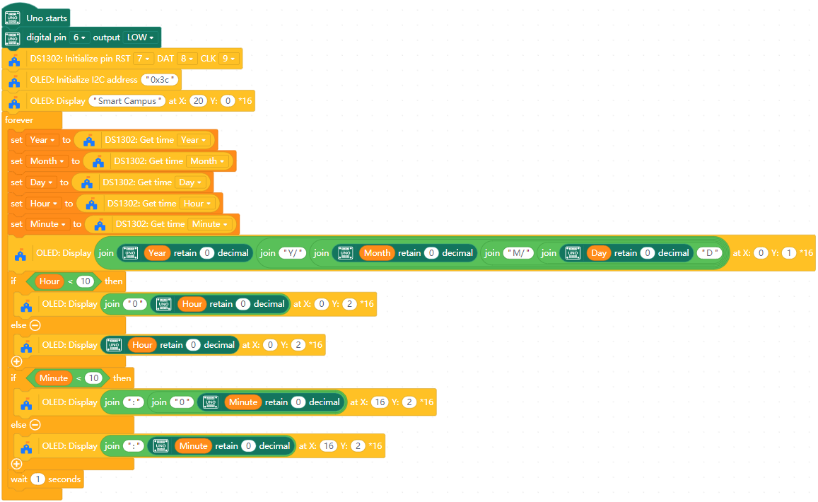
What You Do In Mind+
- Initialize the OLED and clock modules.
- Set the time on the clock module to the current time. (Remove the time-setting blocks after doing so)
- Create the variables
HourandMinute. - In forever:
- Read hour and minute from clock module into
HourandMinute.- Read date (year, month, day) if you want a full display.
- Display them on OLED:
- Line 1: current time (e.g. 08:03).
- Line 2: date (e.g. 2025-01-01).
- For a more proper time display, add a leading 0 if
HourorMinuteare less than 10 (e.g. 8 becomes 08).
- Read hour and minute from clock module into
View Sample Program
- The RTC (DS1302) module is a tiny clock that keeps time even when the main board is off (with its own battery).
- The board simply asks the clock: “What time is it now?” and then chooses how to show it.
- The main takeaway: Time is just another set of numbers (hour, minute, second), which can be used for decisions later.
Goals
- Play a bell sound at the start or end of class automatically using the clock and audio modules.
- Prevent the bell from ringing multiple times within the same minute.
Hardware and Wiring
- DS1302 clock module:
- RST → D7
- DAT → D8
- CLK → D9
- V → 5V
- G → GND
- Audio module:
- RX → D1
- V → 5V
- G → GND
- OLED:
- SCL → SCL
- SDA → SDA
- V → 5V
- G → GND
What You Do In Mind+
- Initialize the OLED, audio, and clock modules.
- Set the clock module to a time convenient to the exercise.
- Create the variables
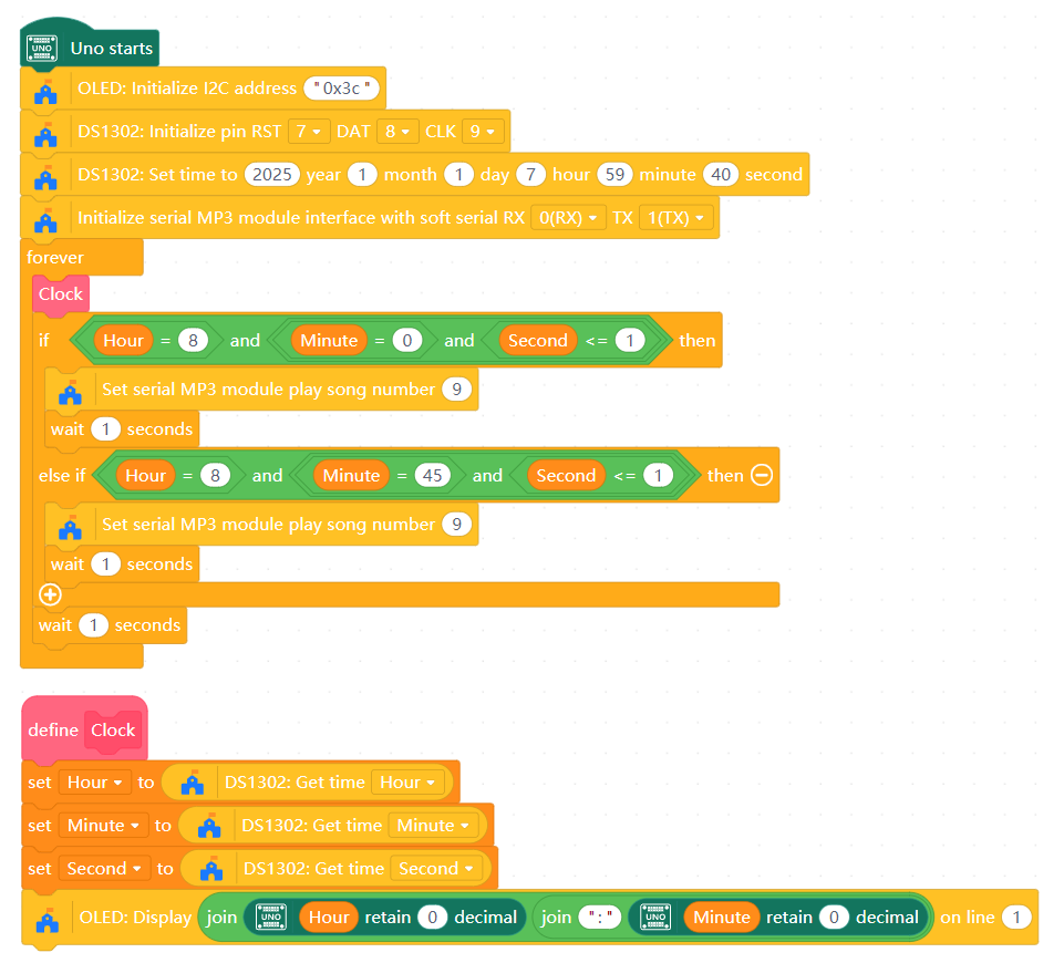
HourandMinute. - Create a function named Clock, reusing the time reading functionality from the Clock exercise.
- Determine a sample set of class times (e.g. 08:00, 08:45, etc.)
- In forever:
- Call your Clock function to get values for
HourandMinute. - If the time equals one of your class times, play the class bell sound using the audio module.
- Call your Clock function to get values for
View Sample Program
- The system acts like an automatic bell ringer:
- It keeps watching the clock.
- When the time matches a schedule, it rings once.
- It is the same idea as automatic flag raising, but here the action is playing a sound instead of moving a servo.
Goals
- Use time to show:
- Current class.
- Next class.
- Optionally combine with an automatic class bell.
Hardware and Wiring
- DS1302 clock module:
- RST → D7
- DAT → D8
- CLK → D9
- V → 5V
- G → GND
- Audio module:
- RX → D1
- V → 5V
- G → GND
- OLED:
- SCL → SCL
- SDA → SDA
- V → 5V
- G → GND
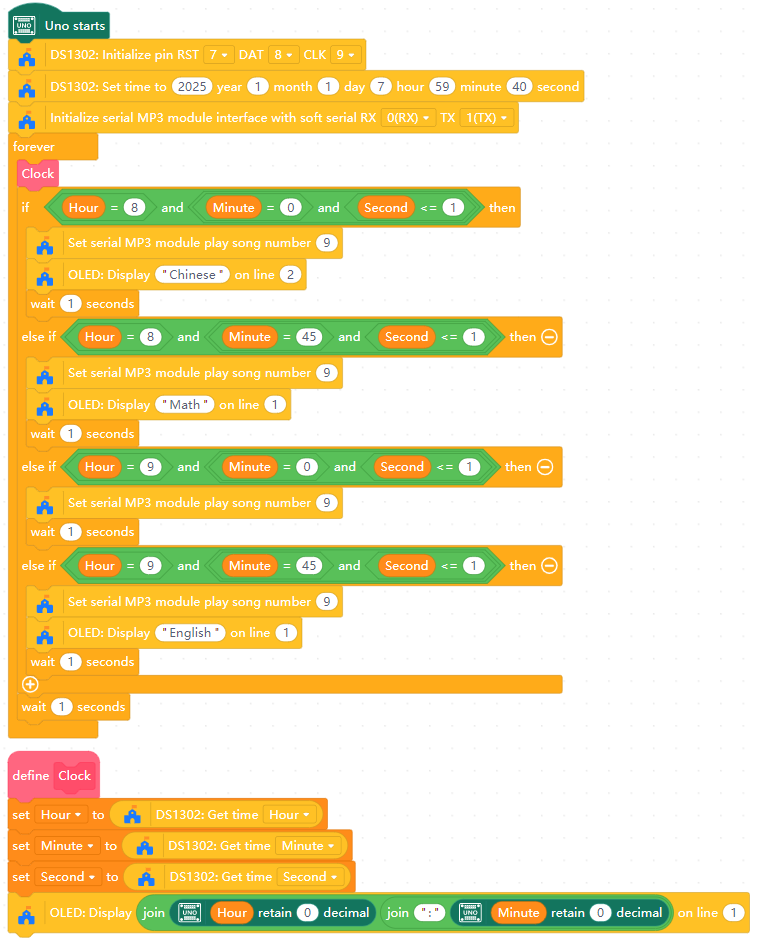
What You Do In Mind+
- Initialize the OLED, audio, and clock modules.
- Set the clock module to a time convenient to the exercise.
- Create the variables
HourandMinute. - Create a function named Clock, reusing the time reading functionality from the Clock exercise.
- Determine a sample set of class times (e.g. 08:00, 08:45, etc.)
- In forever:
- Call your Clock function to get values for
HourandMinute. - Create IF blocks to check for the start times of each class period.
- If one of the time conditions is met, play the sound for the bell on the audio module and display the period subject on the OLED.
- Call your Clock function to get values for
View Sample Program
- The program uses a simple mapping to determine whether the time is the beginning of a new class period.
- It turns this time into human-readable information for teachers and students.
- This is similar to how phone calendars show current events based on the time.
Path F: Identity, Access & Payment
Using identification tools like facial recognition and personal smart cards to control devices and trigger certain events.
Goals
- Use time to show:
- Use an RFID card to decide whether someone can enter the canteen.
- Show “welcome” or “no entry” on OLED and optionally play a voice message.
- Optionally combine with an automatic class bell.
Hardware and Wiring
- RFID reader module:
- SDA → A4
- SCL → A5
- V → 5V
- G → GND
- Audio module:
- RX → D1
- V → 5V
- G → GND
- OLED:
- SCL → SCL
- SDA → SDA
- V → 5V
- G → GND
What You Do In Mind+
- Add RFID and OLED extensions in Mind+.
- Initialize the OLED, audio, and RFID modules.
- In forever:
- Check if there is a card near the RFID module.
- If a card is detected, get its unique ID number, then do one of the following:
- Display the ID number on the OLED screen; or,
- Match the ID number to a set of predetermined ID numbers, with different messages displayed on the OLED for if it matches or doesn't match.
View Sample Program
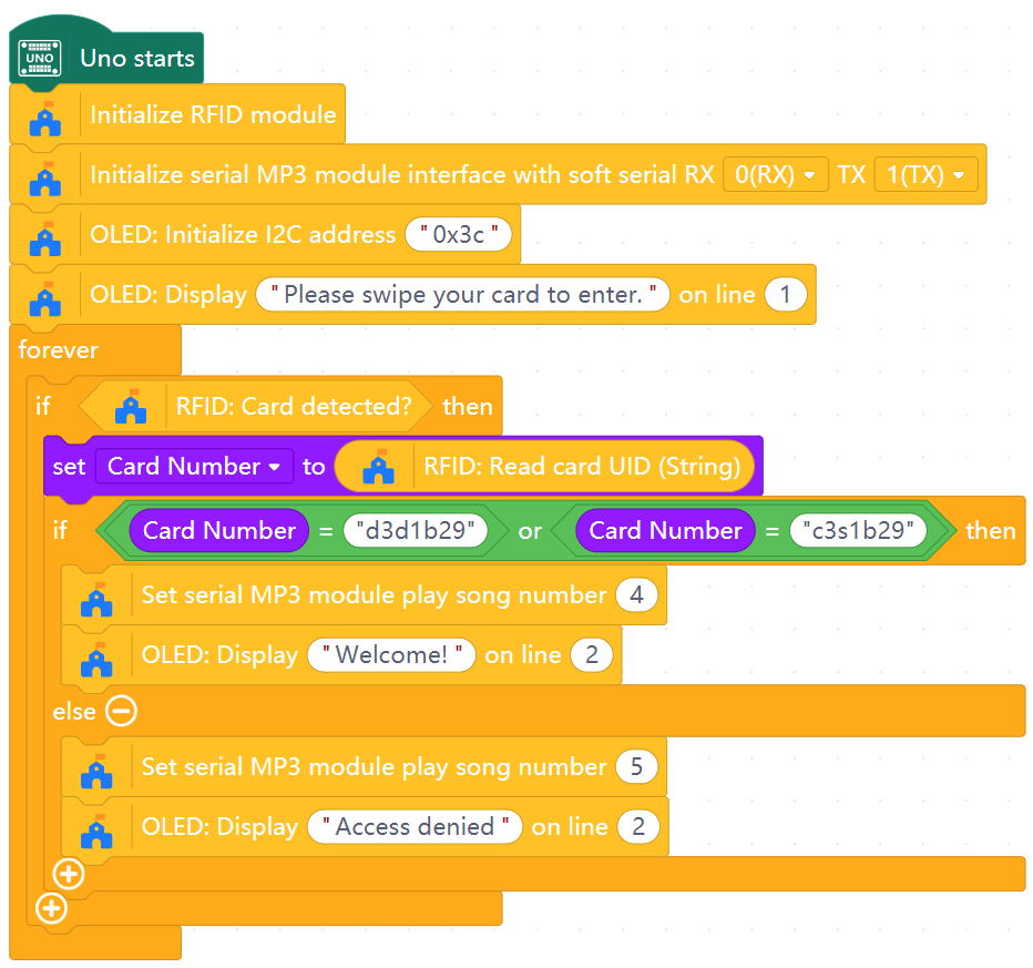
- An RFID card is like an ID card; its UID is a digital name that the board can read.
- The program compares this “name” with a list of allowed names.
- This is the simplest form of access control: "whitelist" vs "others".
Goals
- Use time to show:
- Use an RFID card to decide whether someone can enter the canteen.
- Show “welcome” or “no entry” on OLED and optionally play a voice message.
- Optionally combine with an automatic class bell.
Hardware and Wiring
- RFID reader module:
- SDA → A4
- SCL → A5
- V → 5V
- G → GND
- Audio module:
- RX → D1
- V → 5V
- G → GND
- OLED:
- SCL → SCL
- SDA → SDA
- V → 5V
- G → GND
What You Do In Mind+
- Add RFID and OLED extensions in Mind+.
- Initialize the OLED, audio, and RFID modules.
- For each student card you want to simulate, create:
- A UID string variable (card ID).
- A balance variable, e.g.
Student A balance, with an initial value e.g. 100.
- In forever:
- When a card is detected and its UID matches a known ID:
- Decide a cost for this meal, e.g. 10 (or a random value in a range).
- If
balance≥ cost:- Subtract cost from
balance. - Play a tone to indicate successful payment.
- Show payment amount and card balance on OLED.
- Subtract cost from
- Otherwise:
- Play a different tone to indicate failed payment.
- (Optional) Show “Insufficient balance, please recharge” on OLED.
- When a card is detected and its UID matches a known ID:
View Sample Program
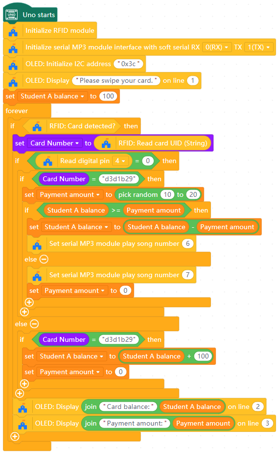
- The card’s UID says “who is buying lunch”.
- The balance variable says “how much money that person still has”.
- The program:
- Checks if there is enough money.
- Either updates the balance and confirms, or refuses the payment.
- This is the logic behind many real-world payment systems.
Goals
- Use AI camera module to recognize faces (students, teacher).
- Open a servo-controlled door when a known face is seen; treat unknown faces as “illegal entry”.
- Play voice messages and/or show names on OLED.
Hardware and Wiring
- AI module:
- RX → A2
- TX → A3
- V → 5V
- G → GND
- 180-degree servo:
- S → D11
- V → 5V
- G → GND
- Audio module:
- RX → D1
- V → 5V
- G → GND
- OLED:
- SCL → SCL
- SDA → SDA
- V → 5V
- G → GND
What You Do In Mind+ (Face Recording)
- Add AI and OLED extensions in Mind+.
- Initialize the OLED, audio, and AI modules.
- Use AI camera’s own screen/buttons to:
- Switch into face recognition mode.
- Record up to 4 faces (IDs 1–4):
- Point camera at a face; a frame and ID0 will appear.
- Press the record key to save as ID1, ID2, etc.
- Enable “multi-learning” if needed so it can learn the same person in different angles.
- Use a variable ID to store the face ID data from the AI module.
- Use an IF block to match ID to people’s names and display the name on the OLED screen.
View Sample Program
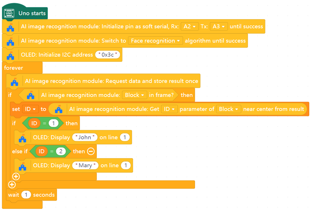
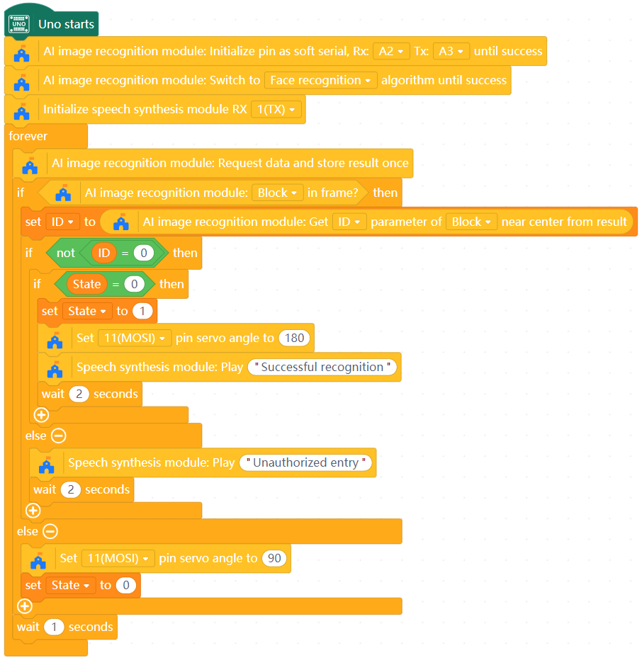
What You Do In Mind+ (Gate Control)
- Initialize the OLED, audio, and AI modules.
- In forever:
- Ask AI module for recognition result.
- Read recognized face ID into a variable, for example
ID. - If
IDis one of the known IDs (1–4):- Open the door servo (set to open angle).
- Show the person’s name on OLED.
- Play a welcome voice such as “Recognition successful, please enter”.
- If no face or ID 0:
- Close the door (set servo back to closed angle).
- Play or display “Unauthorized entry”.
- To avoid repeated voice when the face stays in front, use a variable
State(0/1) to remember whether a message has already been played for the current face.
View Sample Program
- The AI module does the hard work of “seeing” faces and only tells the board a simple ID number.
- The board then uses this ID number just like an RFID UID:
- “ID 1 → open the door.”
- “ID 0 → unknown → do not open.”
- This is another form of access control, but using a person’s face instead of a card.
Goals
- Use face recognition to sign in when students arrive at school.
- Keep track of who has signed in and who has not.
- Use clock module to decide whether sign-in is on time or late.
Hardware and Wiring
- AI module:
- RX → A2
- TX → A3
- V → 5V
- G → GND
- Audio module:
- RX → D1
- V → 5V
- G → GND
- DS1302 clock module:
- RST → D7
- DAT → D8
- CLK → D9
- V → 5V
- G → GND
- OLED:
- SCL → SCL
- SDA → SDA
- V → 5V
- G → GND
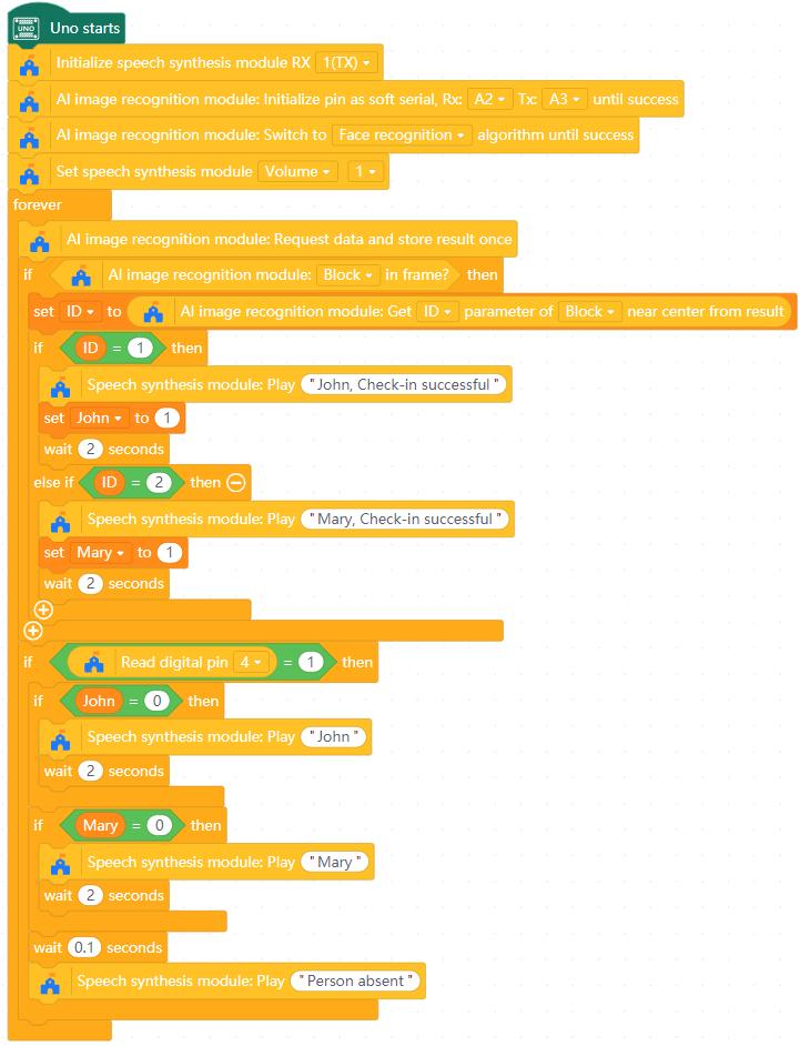
What You Do In Mind+ (Sign-in)
- Add AI and OLED extensions in Mind+.
- Initialize the OLED, audio, and AI modules.
- Reuse the face IDs recorded in the previous exercise.
- Create a sign-in variable for each student, for example
personA,personB, etc. with initial value 0. - In forever:
- Ask AI module for recognition result.
- If ID = 1 and
personA= 0:- Set
personAto 1. - Play voice: “Student A check-in successful”.
- Set
- Repeat for ID = 2 and personB, etc.
- If ID does not match a recognized value, play voice “Absent”.
View Sample Program
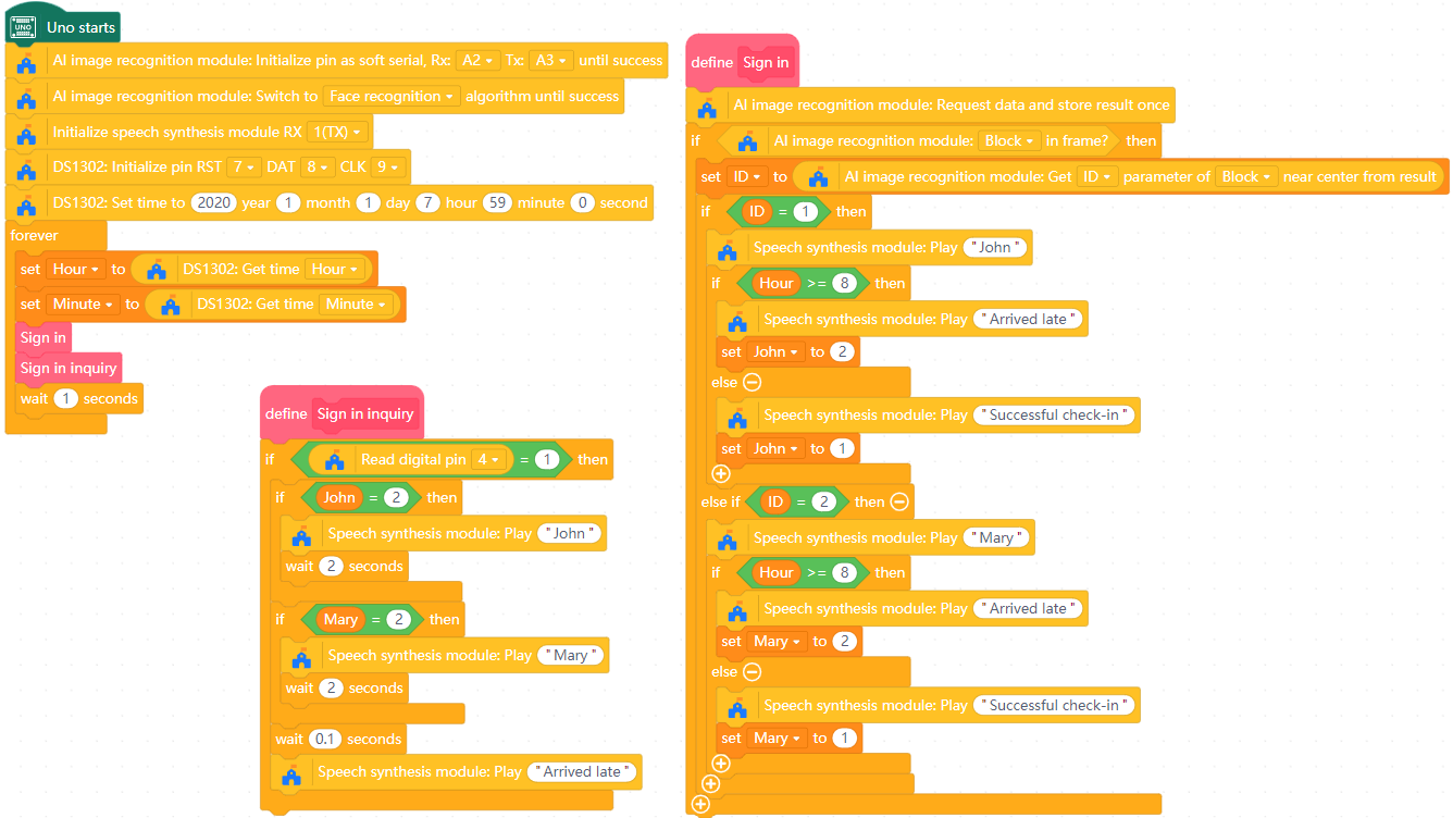
What You Do In Mind+ (Attendance Query)
- Initialize the OLED, audio, clock, and AI modules.
- Create the function blocks Sign in and Sign in inquiry.
- In the Sign in function:
- Get the ID information from the AI module.
- If ID is a recognized value, play a voiceline of the person’s name, followed by a declaration of whether they arrived on time or late (according to clock data).
- Depending on whether the person arrived late or on time, set their variable (
personA,personB, etc.) to record their status.
- In the Sign in inquiry function:
- Use a button press to trigger the following events:
- Check the status of the personal variables (
personA,personB, etc.) - If any of them are marked as late (e.g. value = 2), play a voiceline of their name and declare that they arrived late.
- Check the status of the personal variables (
- Use a button press to trigger the following events:
- In forever:
- Get Hour and Minute data from the clock module (to be used in the Sign in function).
- Add function calls for Sign in and Sign in inquiry.
- Wait 1 second.
View Sample Program
- Each student is represented by:
- A face ID from the AI module.
- A sign-in variable, 0 or 1.
- When the student’s face appears:
- The program marks them as signed in.
- It checks the clock to see if they are on time or late.
- Later, the teacher can press a button to hear which students are still missing.
- This is a simple digital version of taking attendance with built-in time judgement.