Getting Started
Software & Drivers
Before building, ensure your environment is ready:
- Install Mind+: Download from the official website. Switch to "Upload Mode".
- Select Board: Choose "Arduino Uno" (or the specific Matrix Controller board provided).
- Add Library: Go to Extensions > User Library > Import the "Matrix Magic Cube" file.
- Install Drivers: Connect via USB. If the COM port is not found, click "Install Serial Driver" in Mind+.
Hardware Basics
- Ports 1–4: Universal ports for Motors and Sensors.
- Special Ports: Some modules (like Laser Range) require specific ports (e.g., Port 4). Check specific lessons.
- Power: Always turn on the battery box switch when running motors.
- Connect a DC Motor to Port 1.
- In Mind+, drag a forever loop.
- Inside, set Motor (Port 1) speed to 150.
- Upload; confirm that the motor spins continuously.
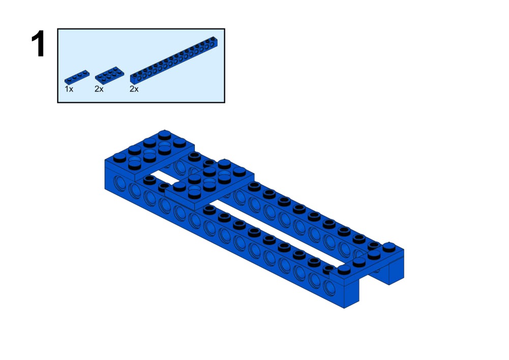
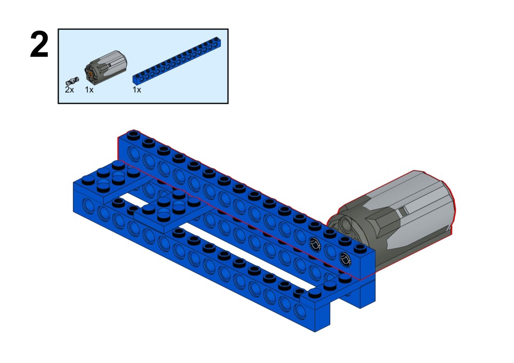
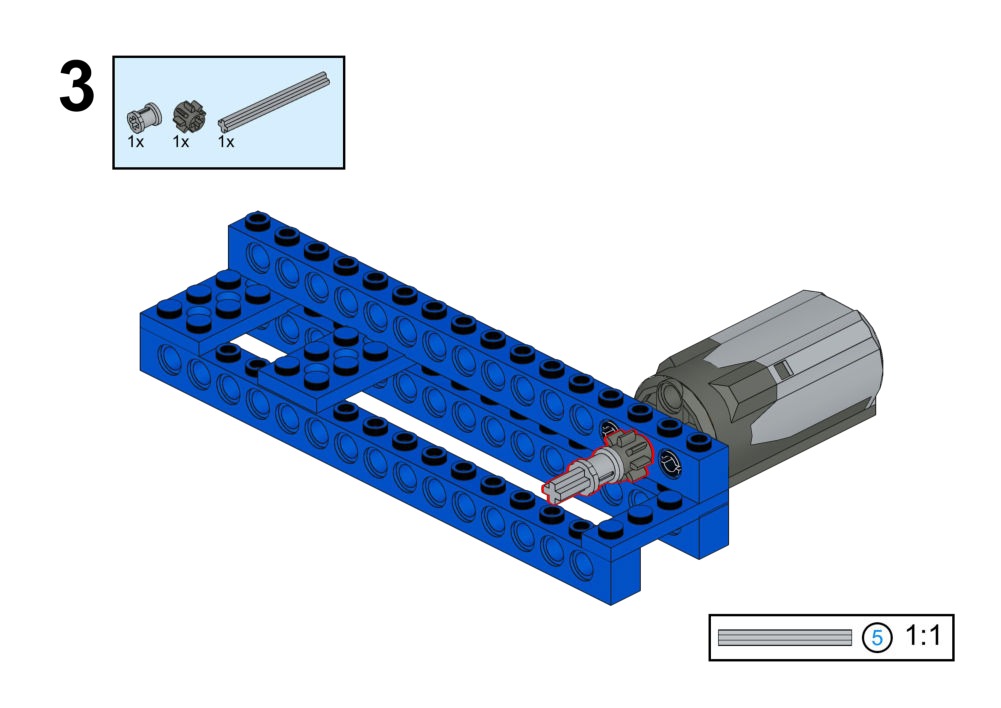
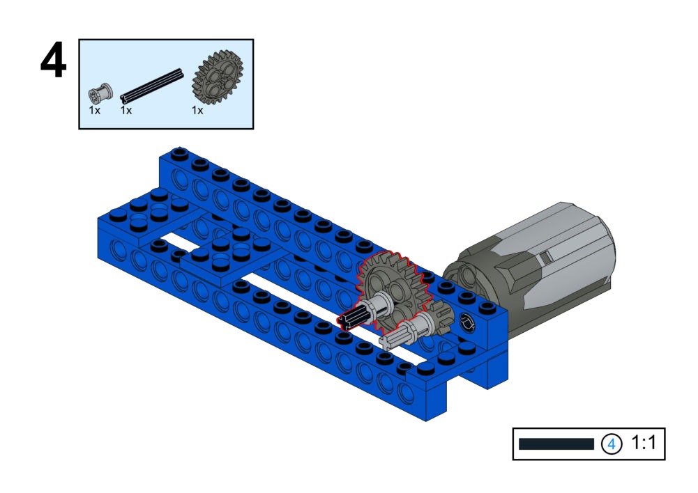
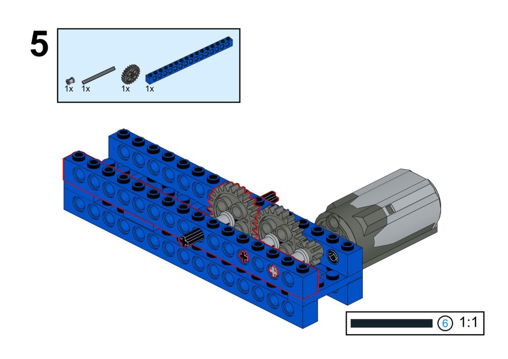
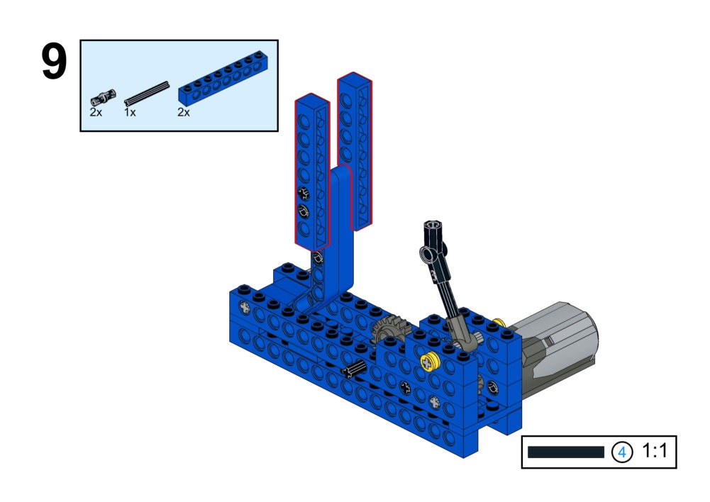
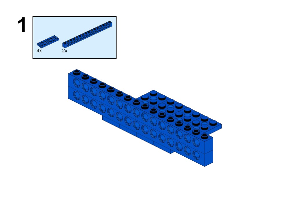
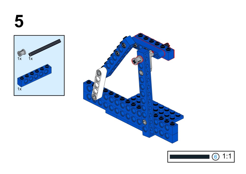
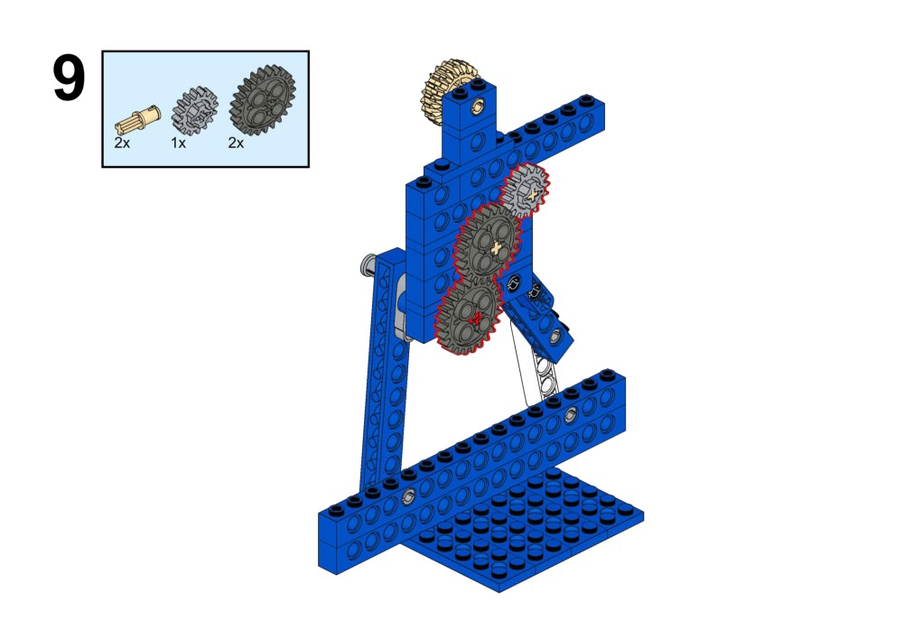
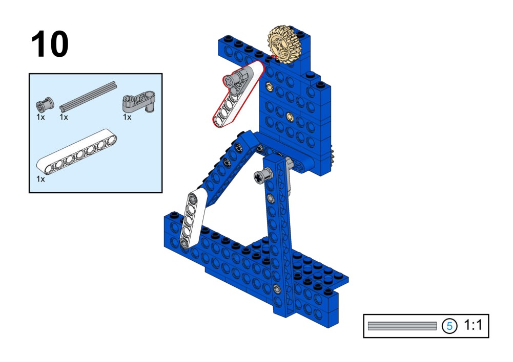
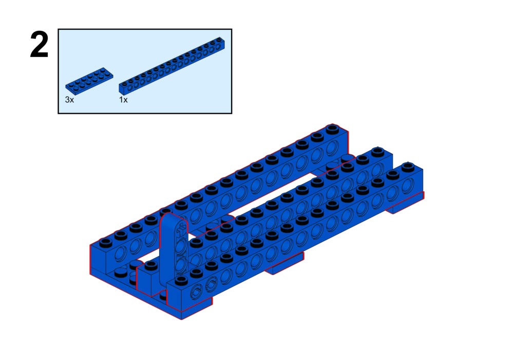
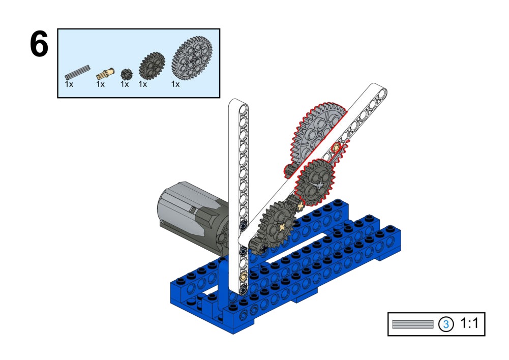
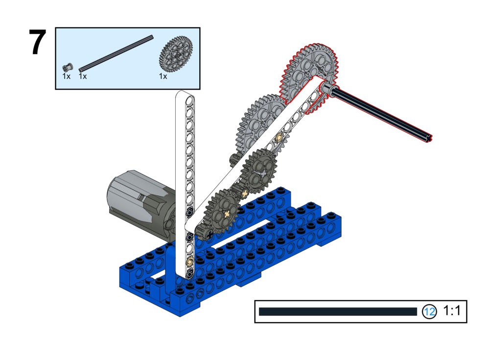
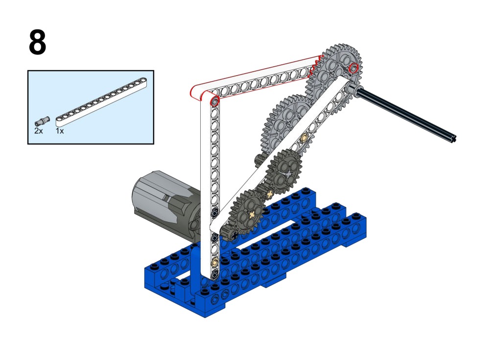
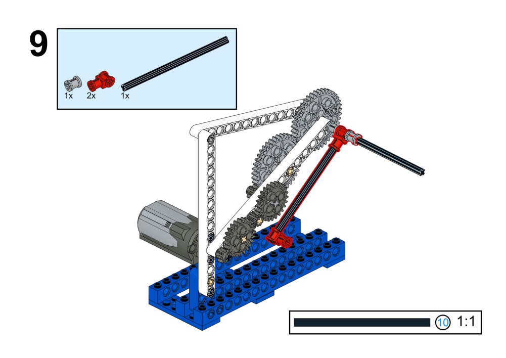
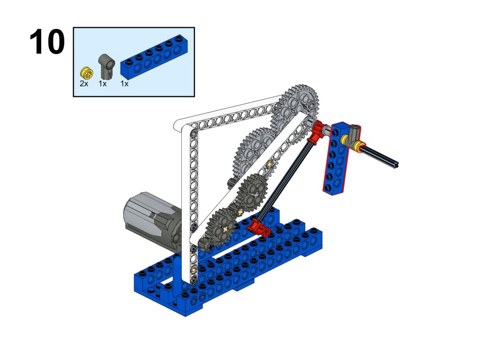
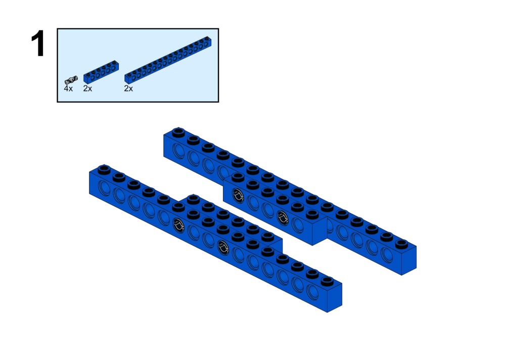
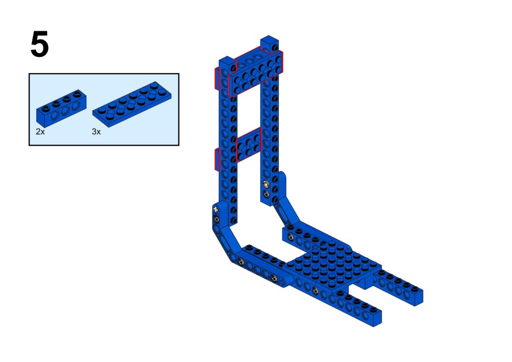
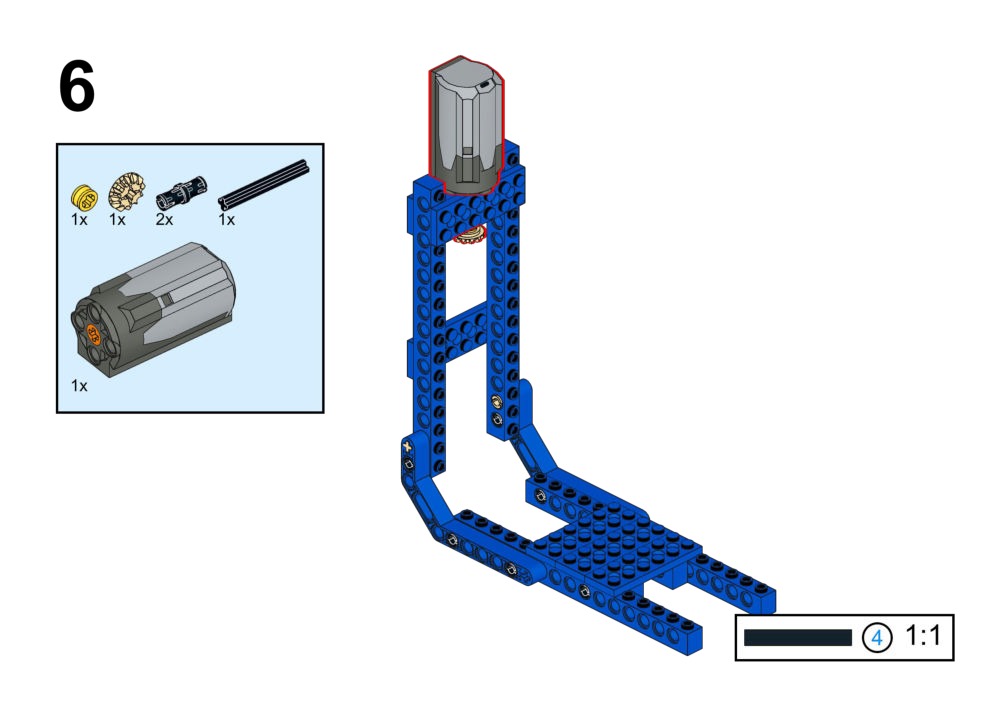
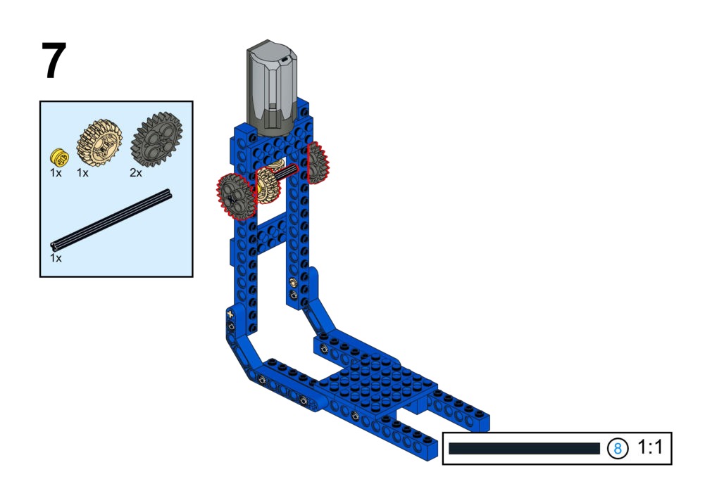
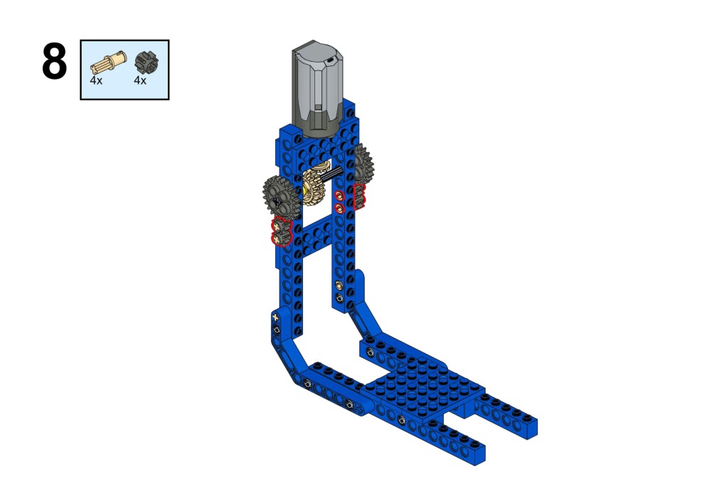
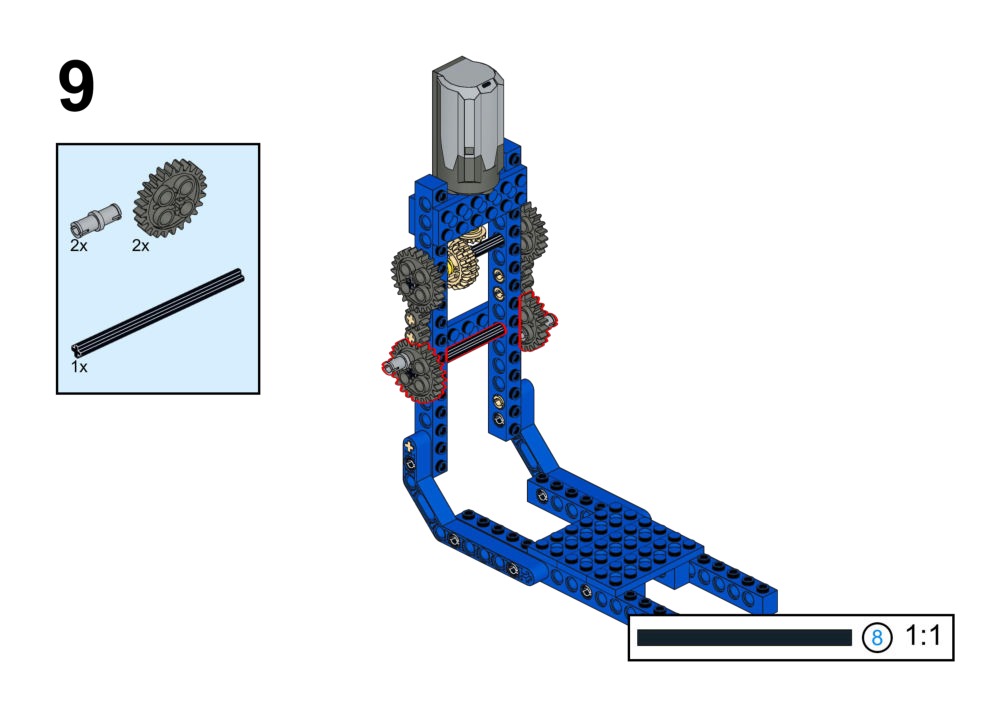
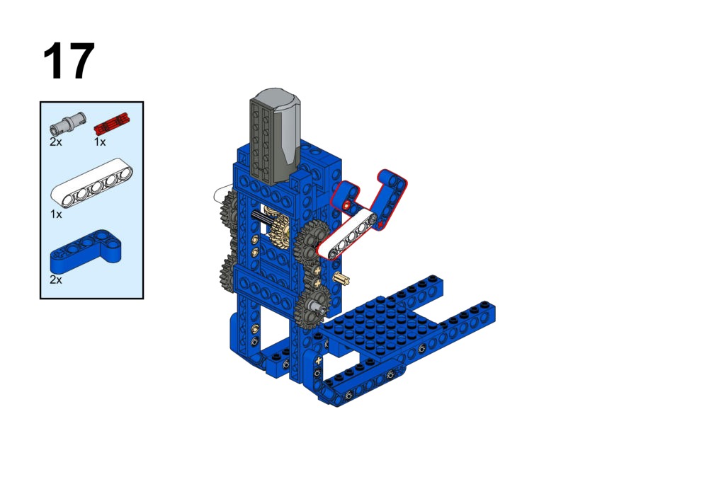
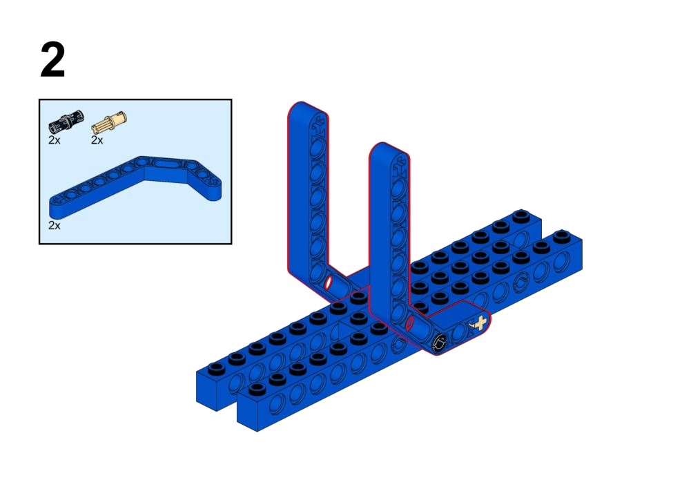
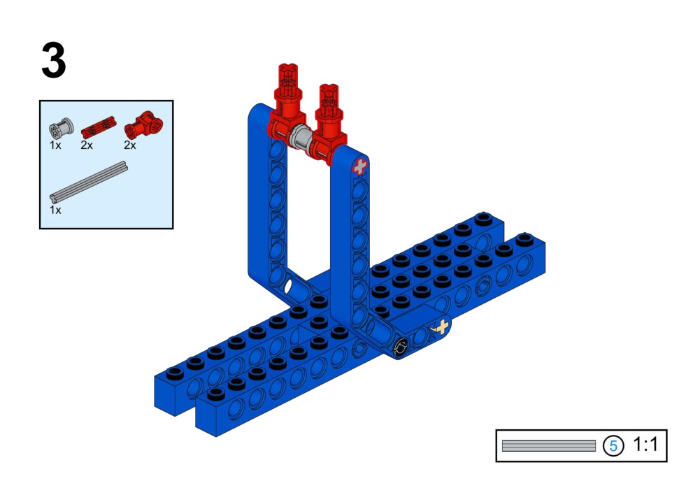
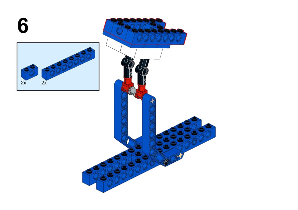
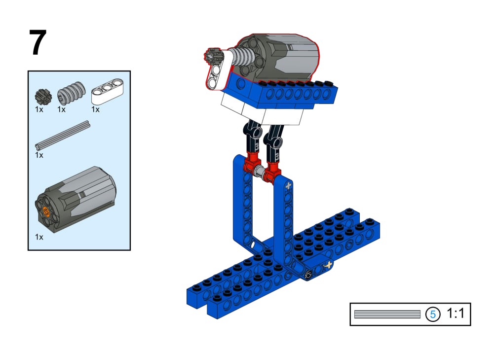
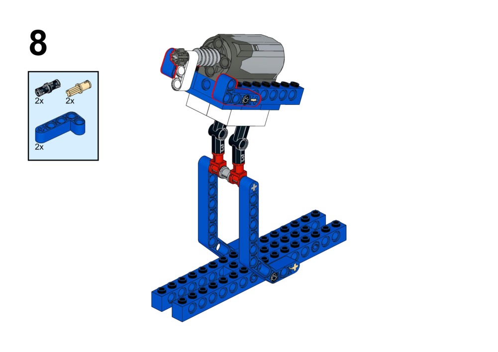
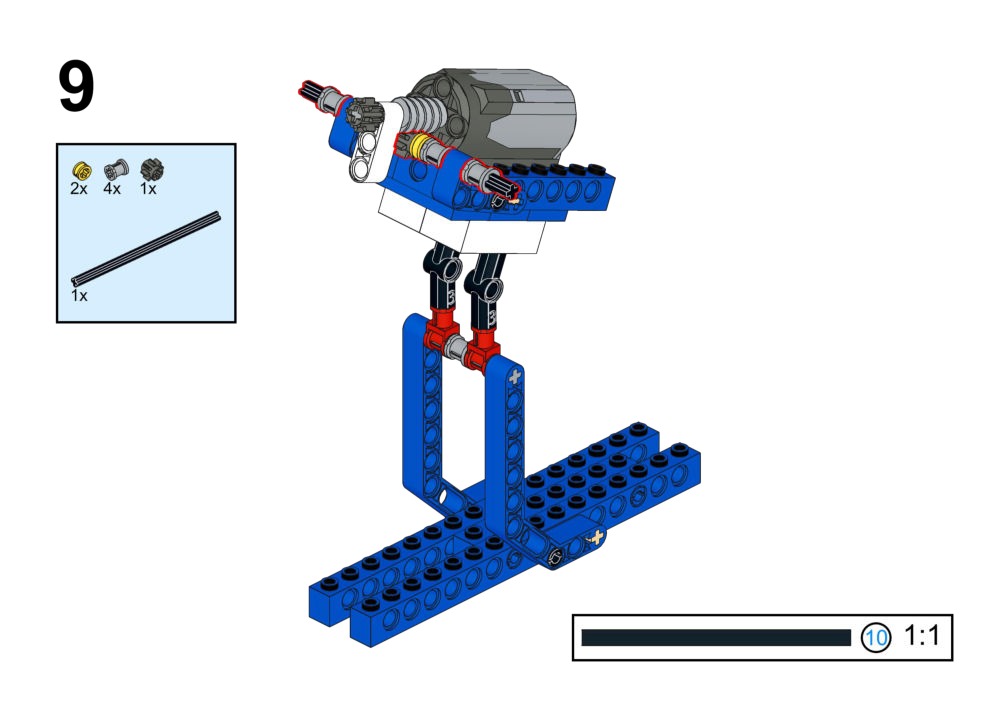
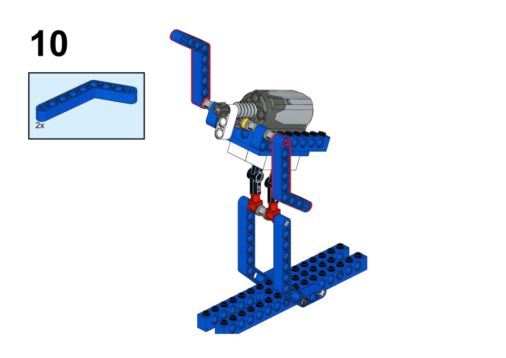
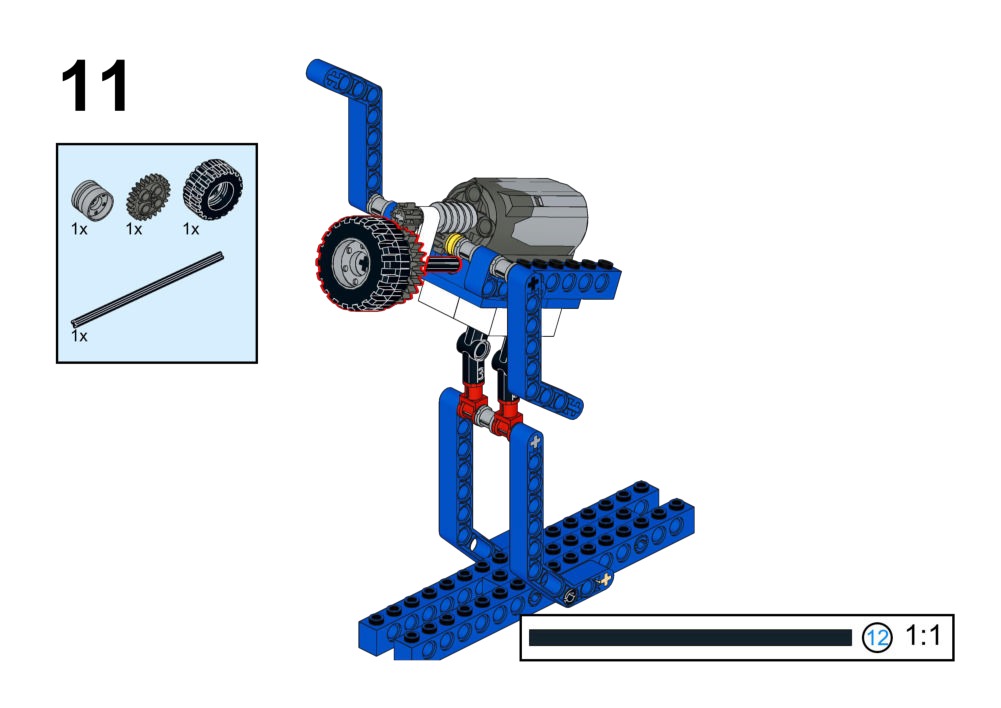
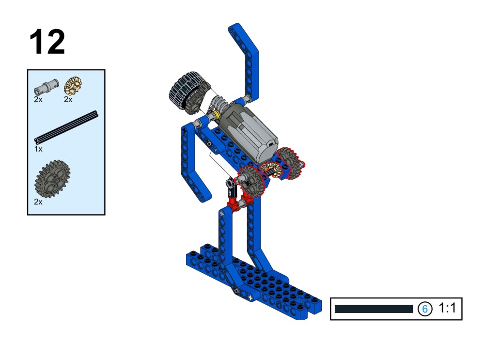
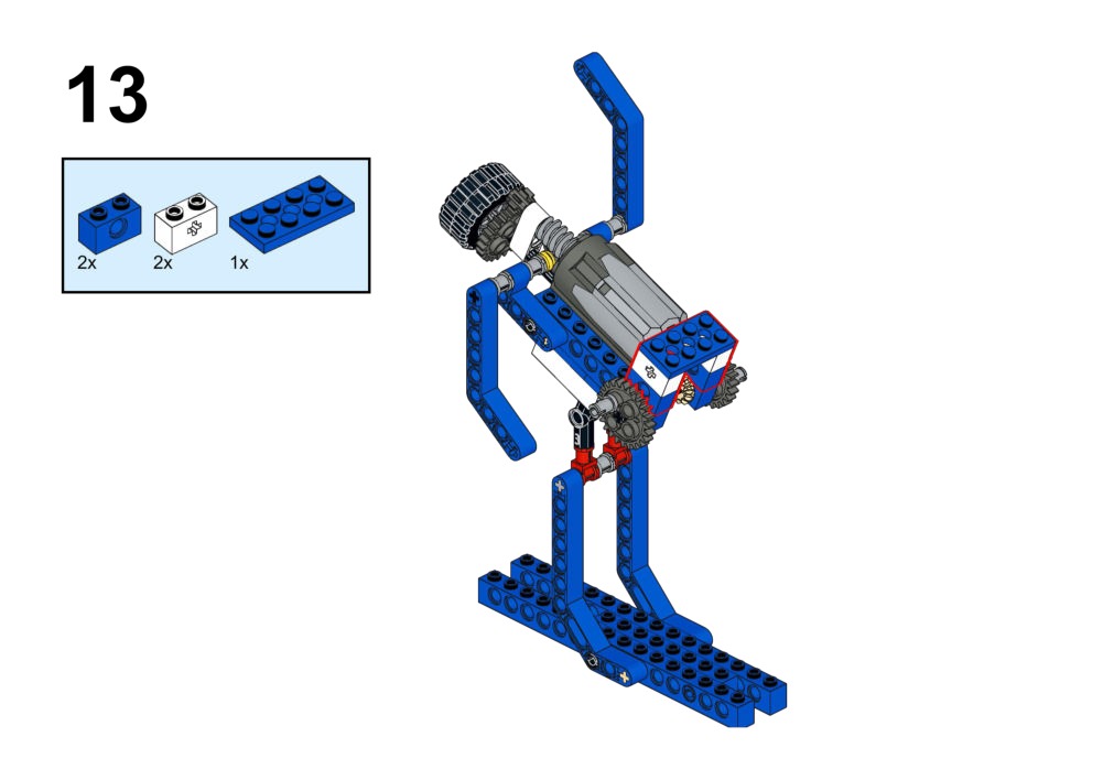
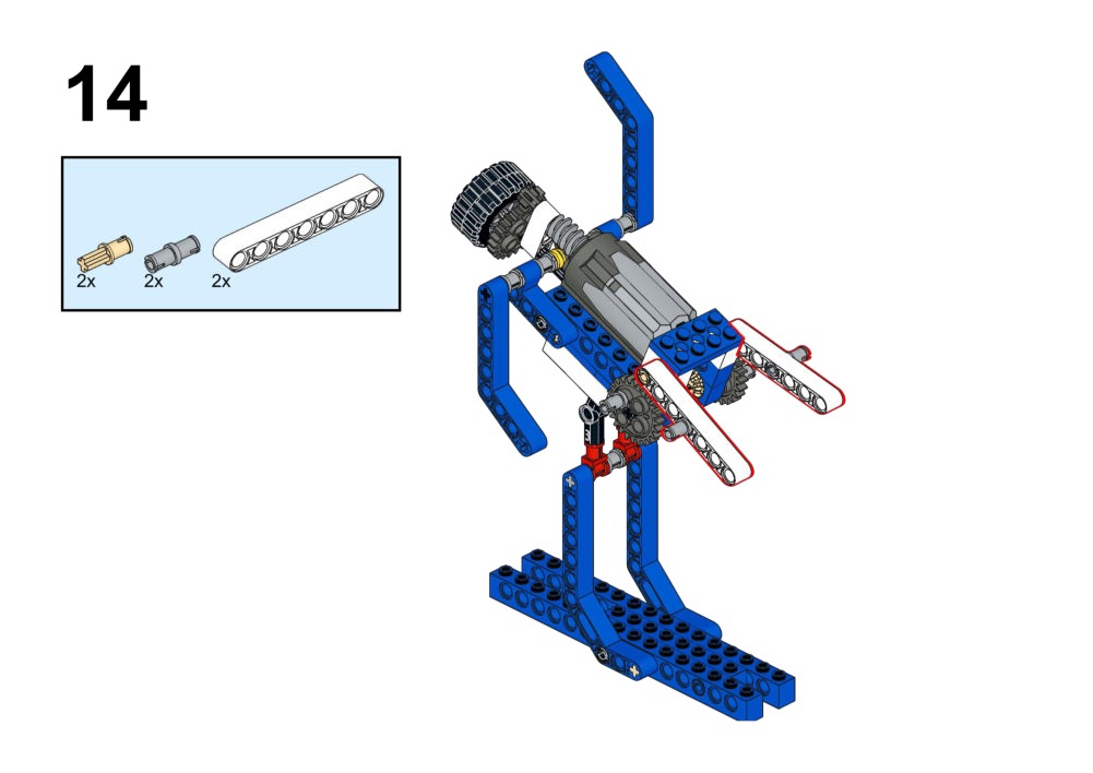
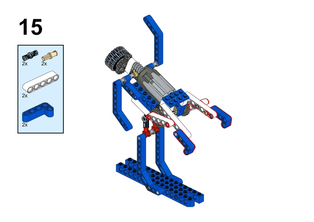
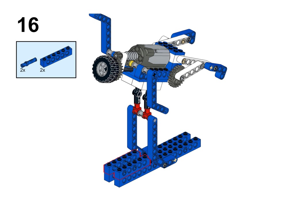
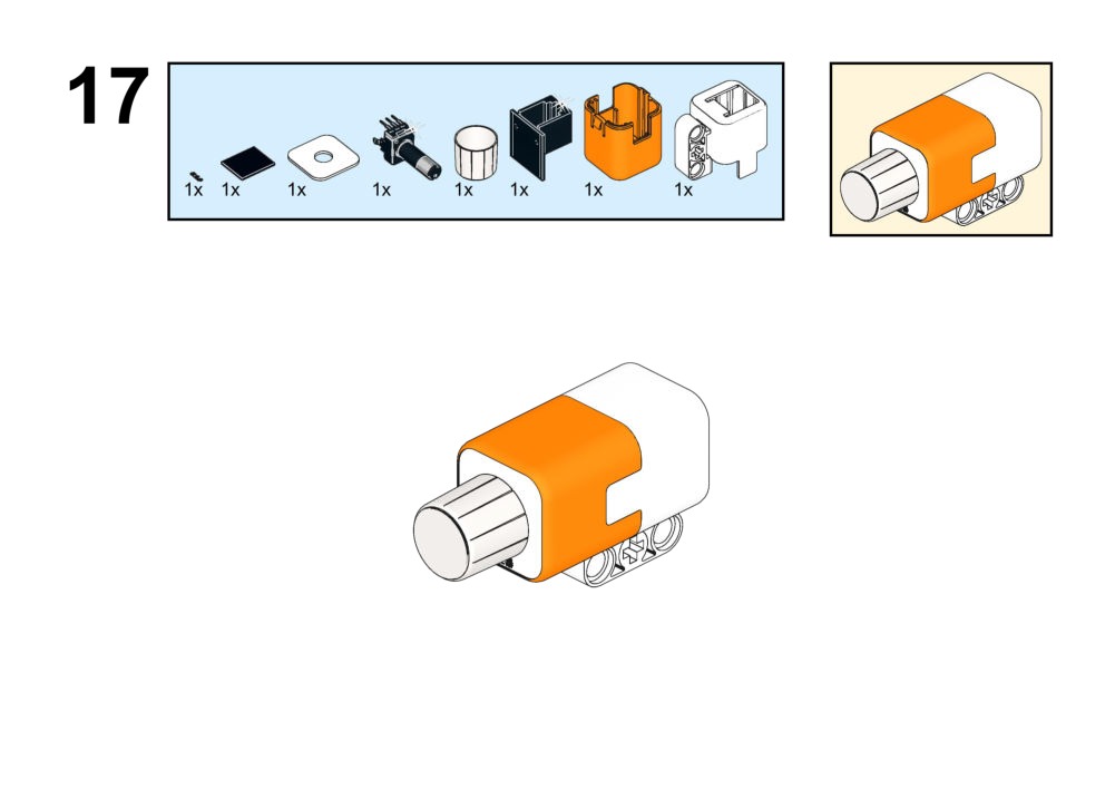
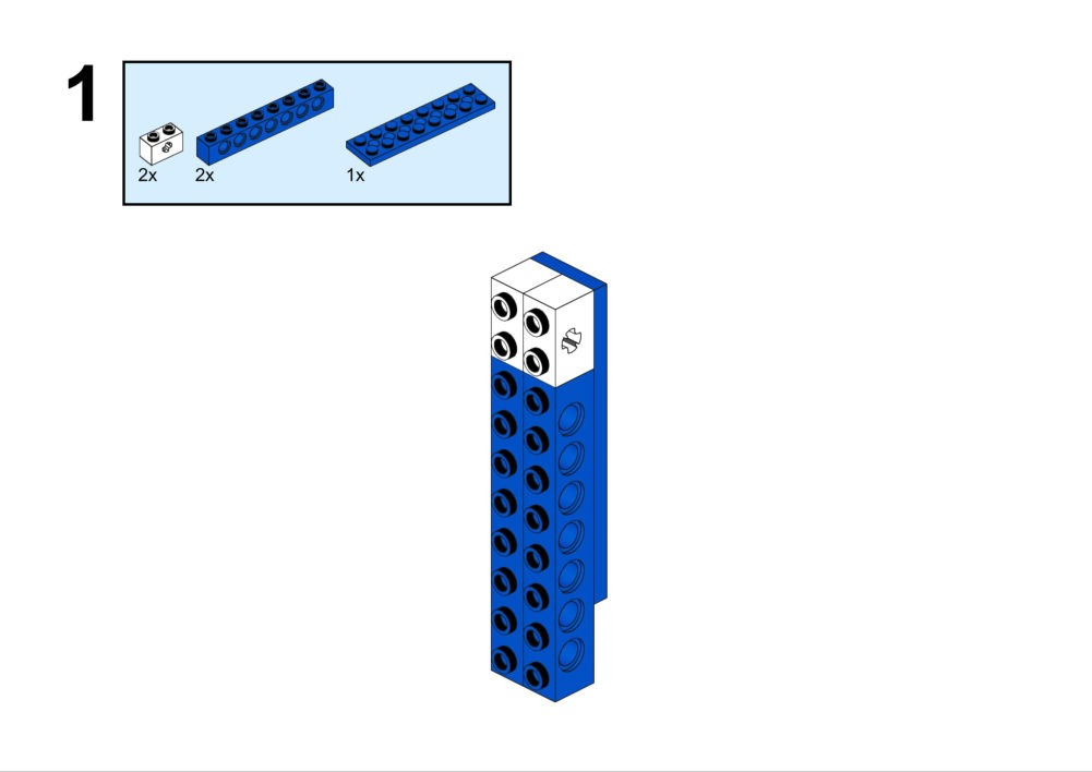
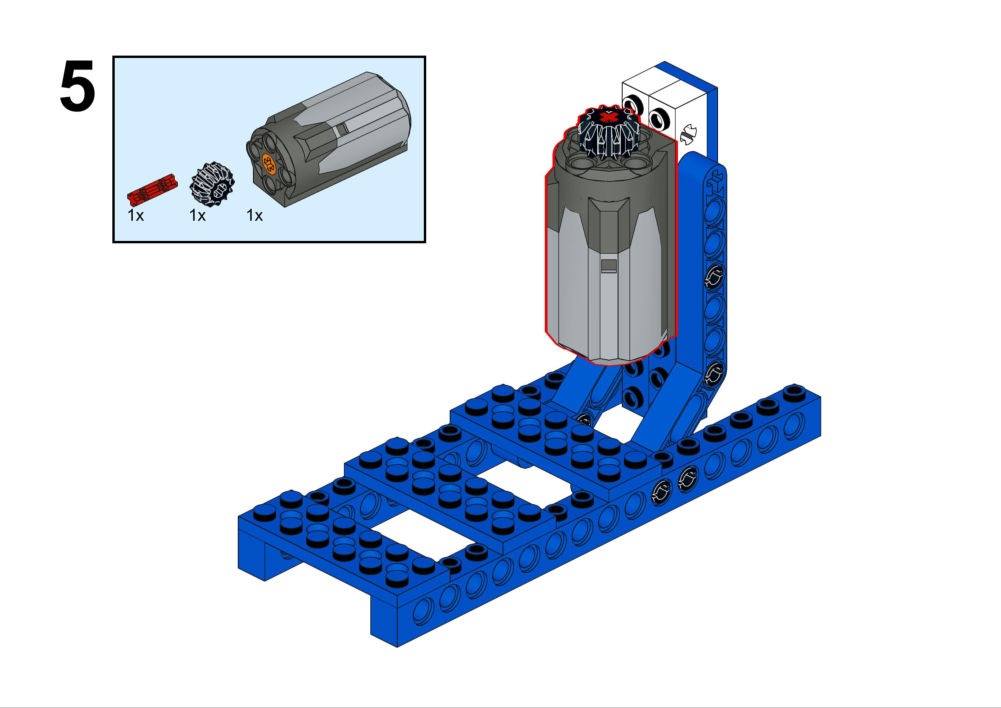
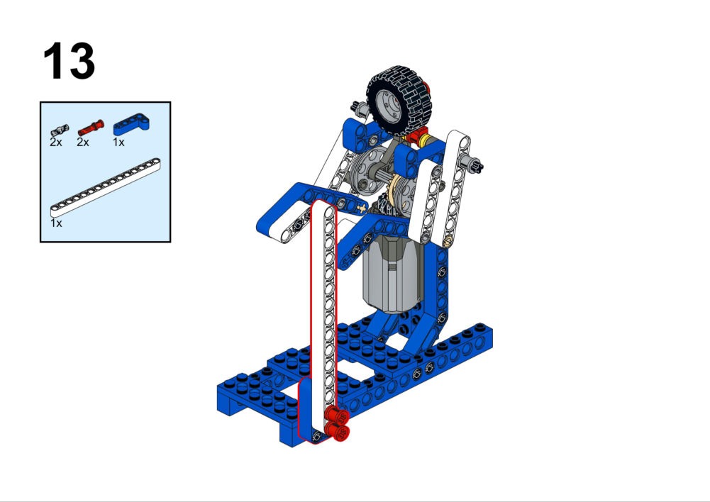
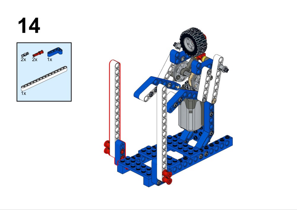
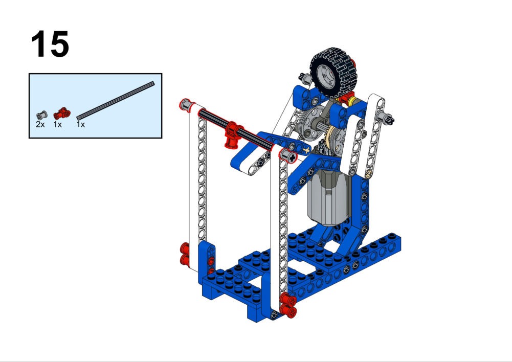
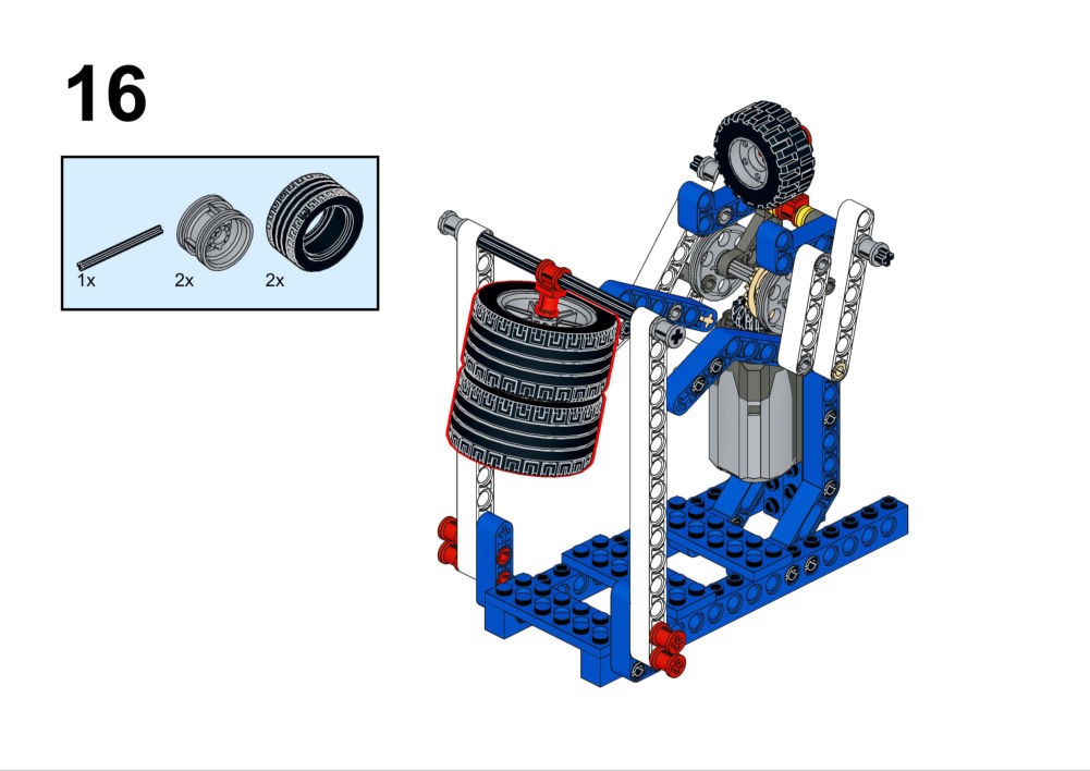
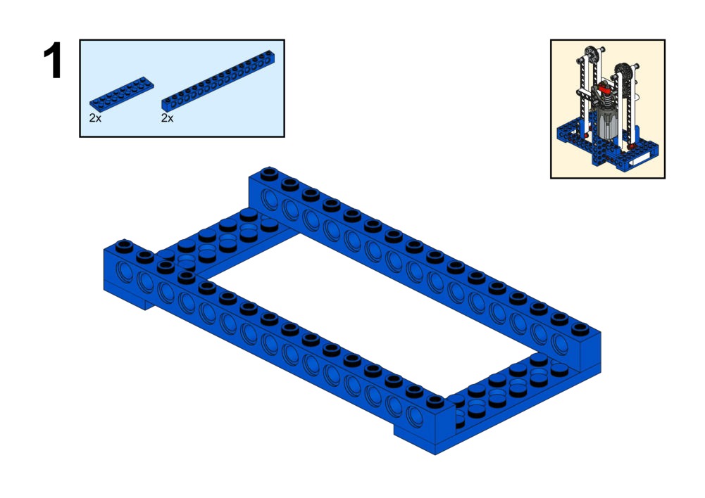
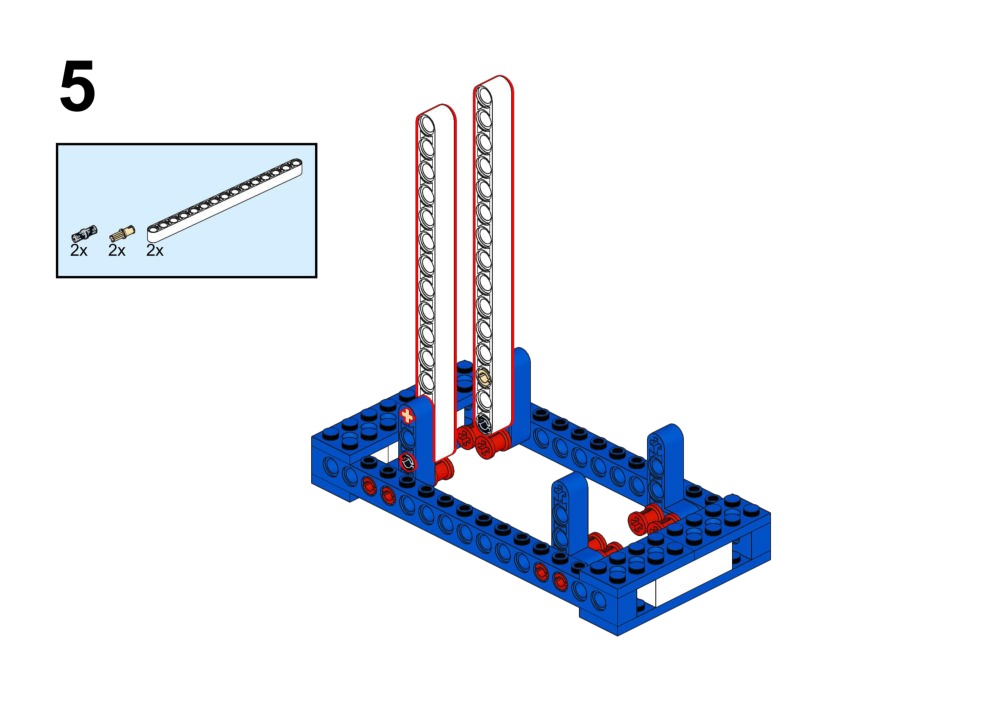
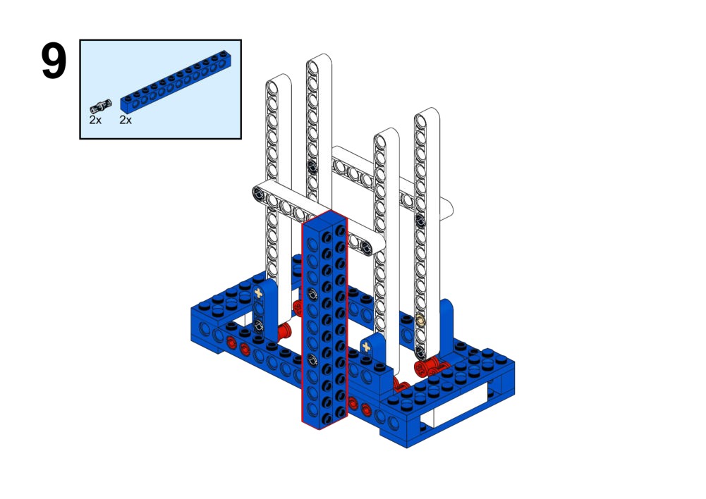
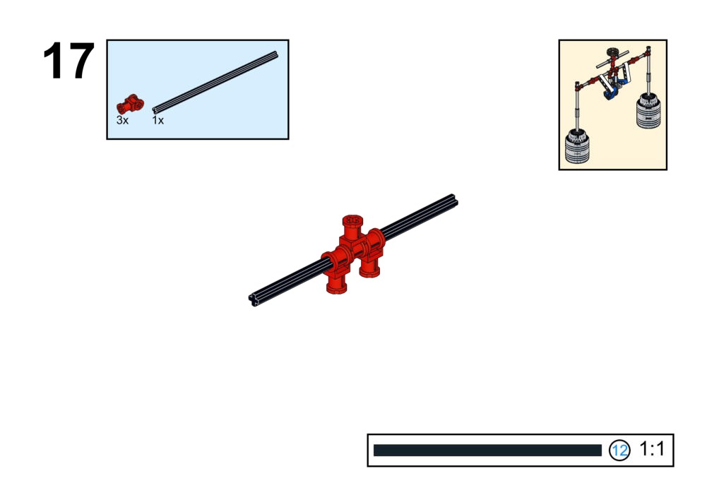
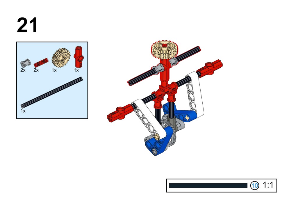
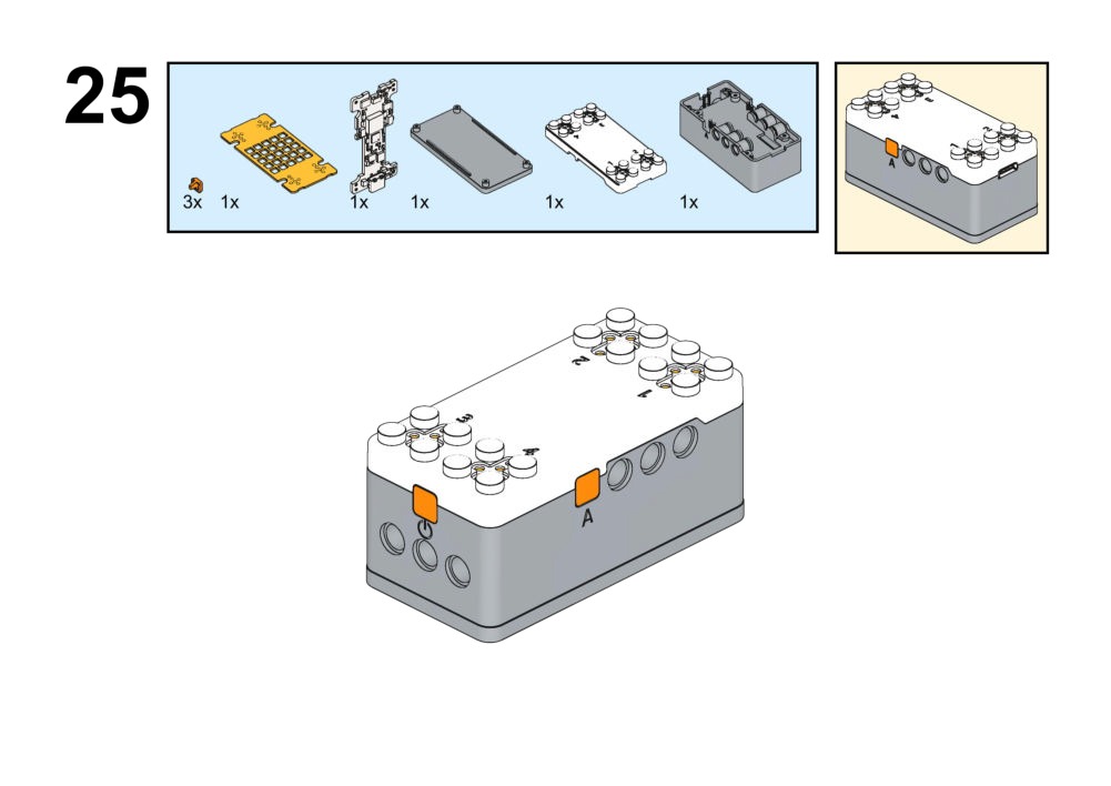
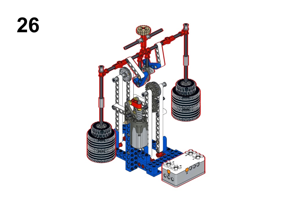
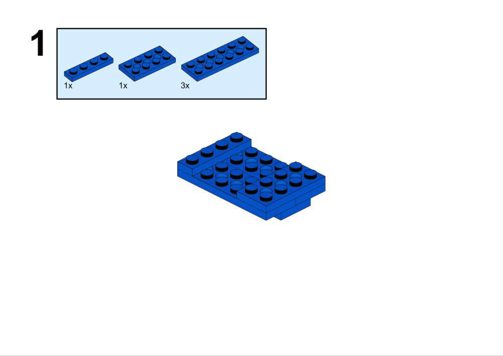
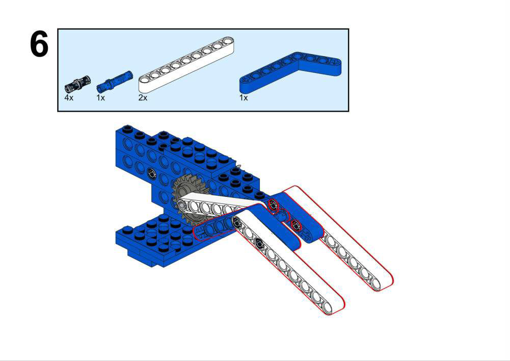
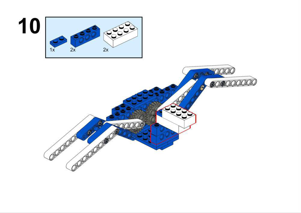
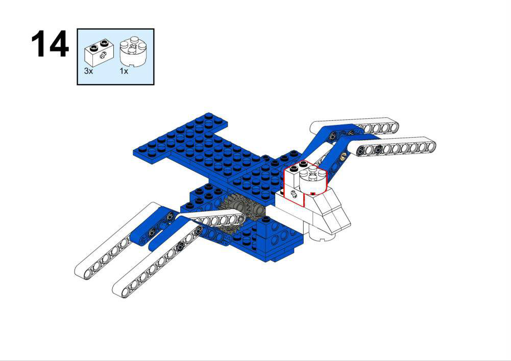
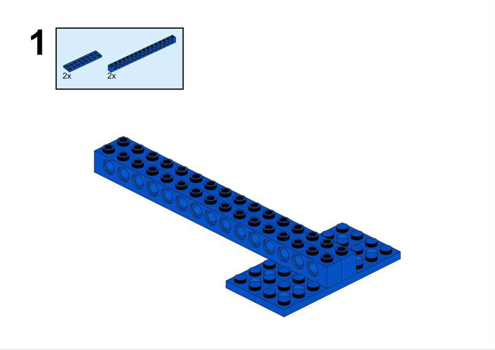
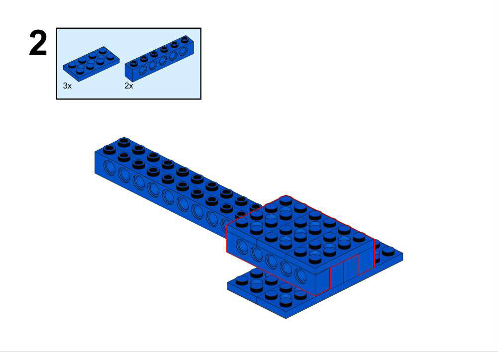
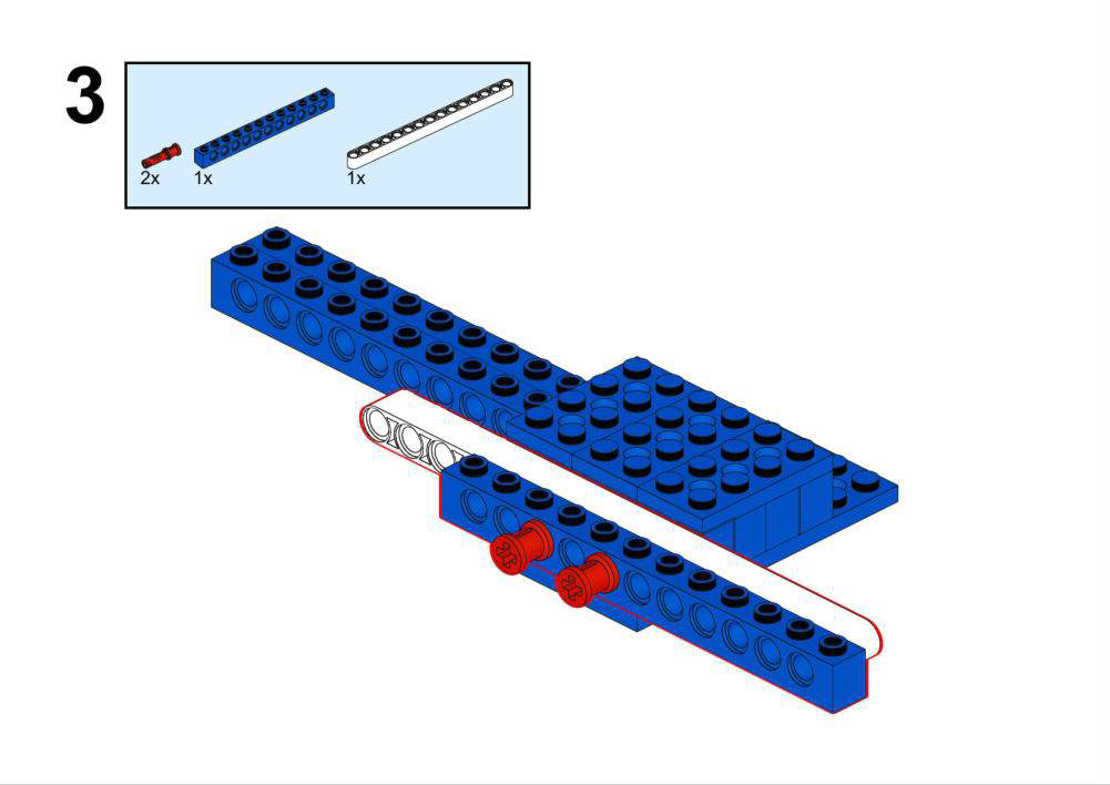
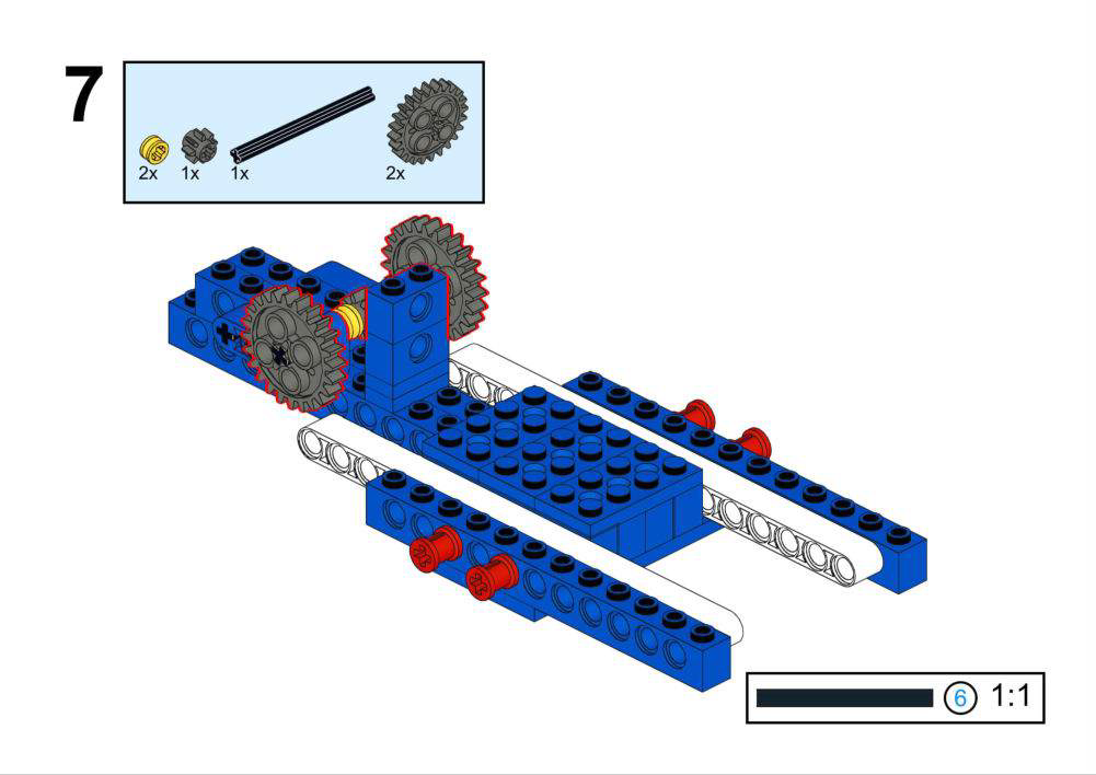
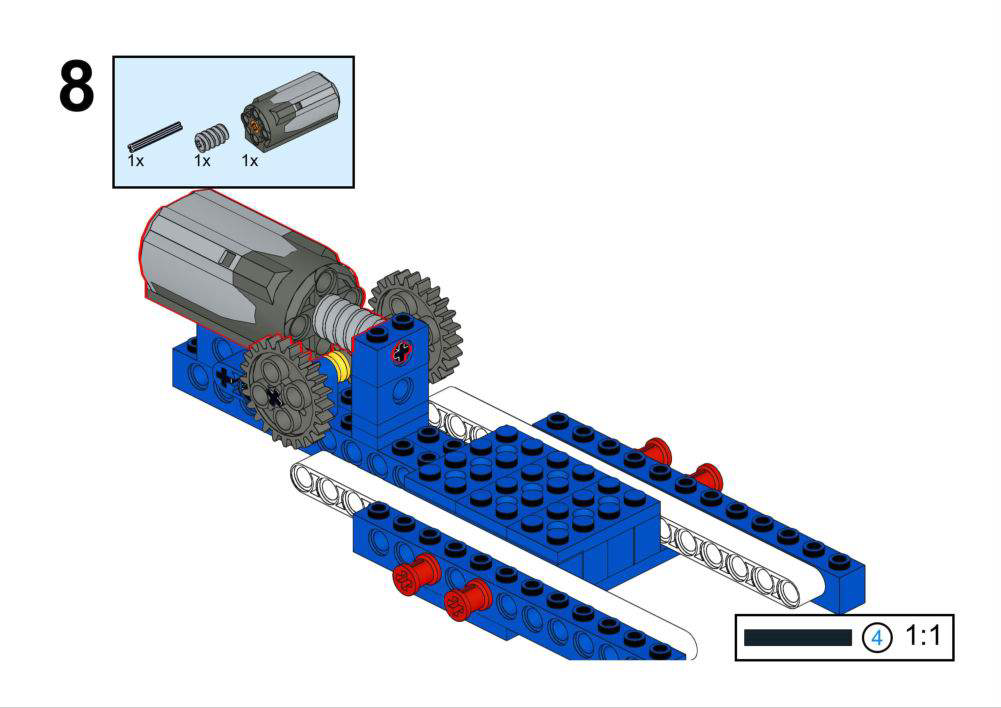
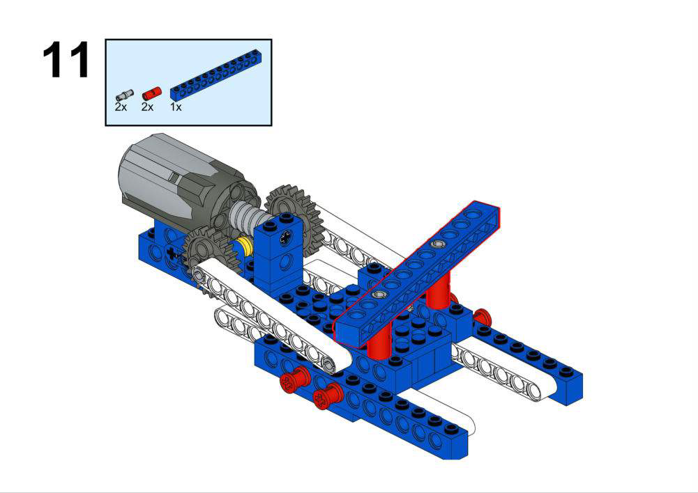
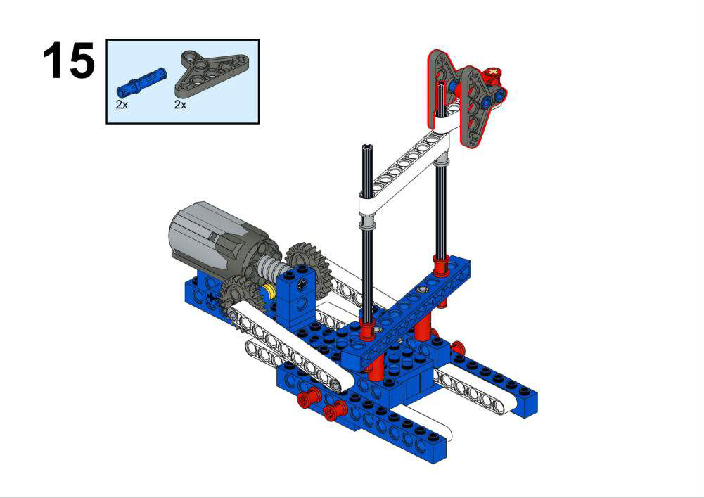
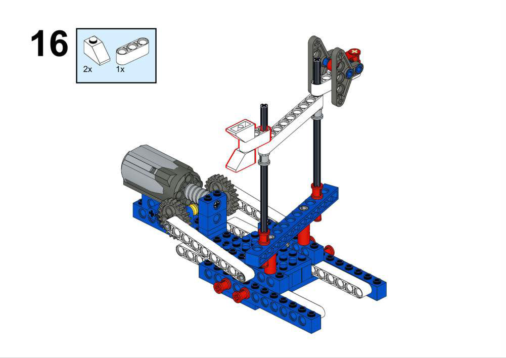
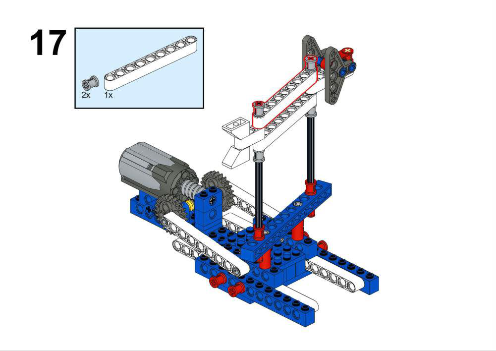
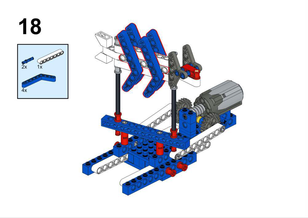
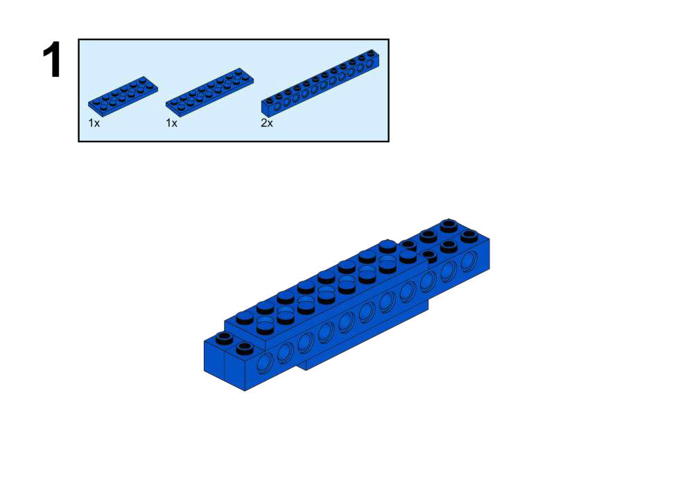
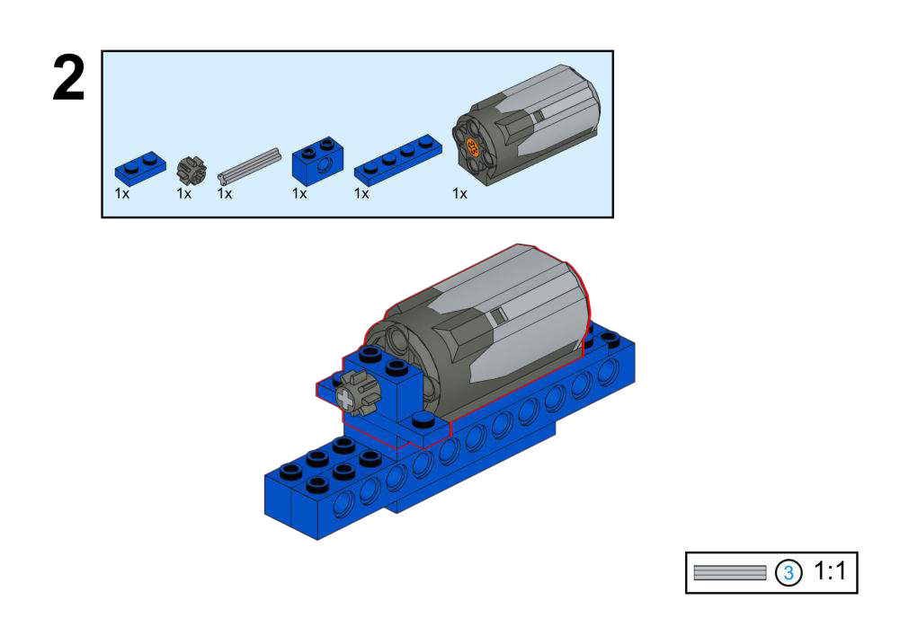
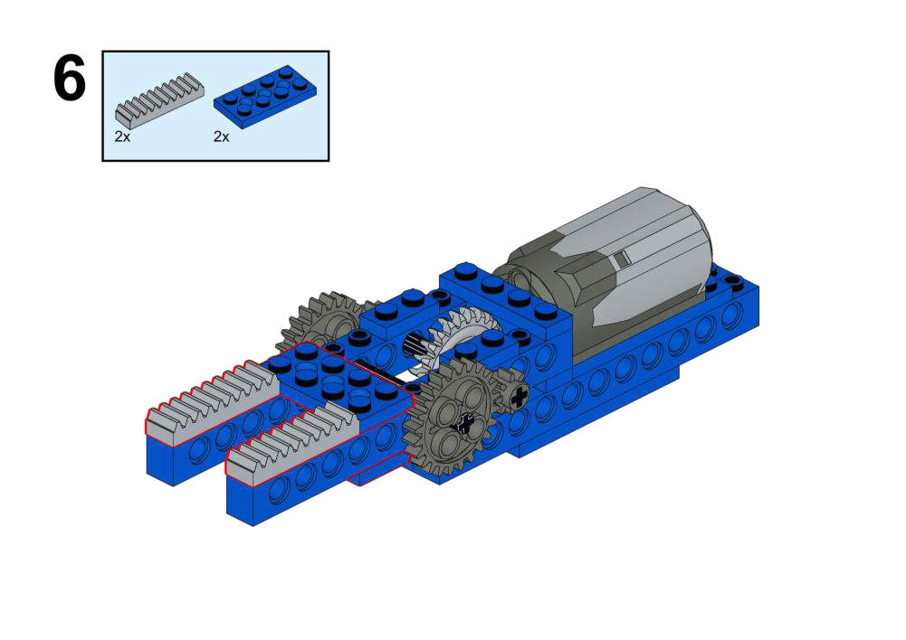
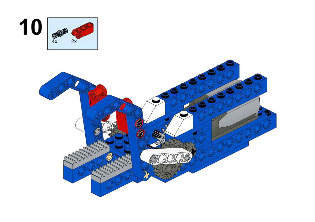
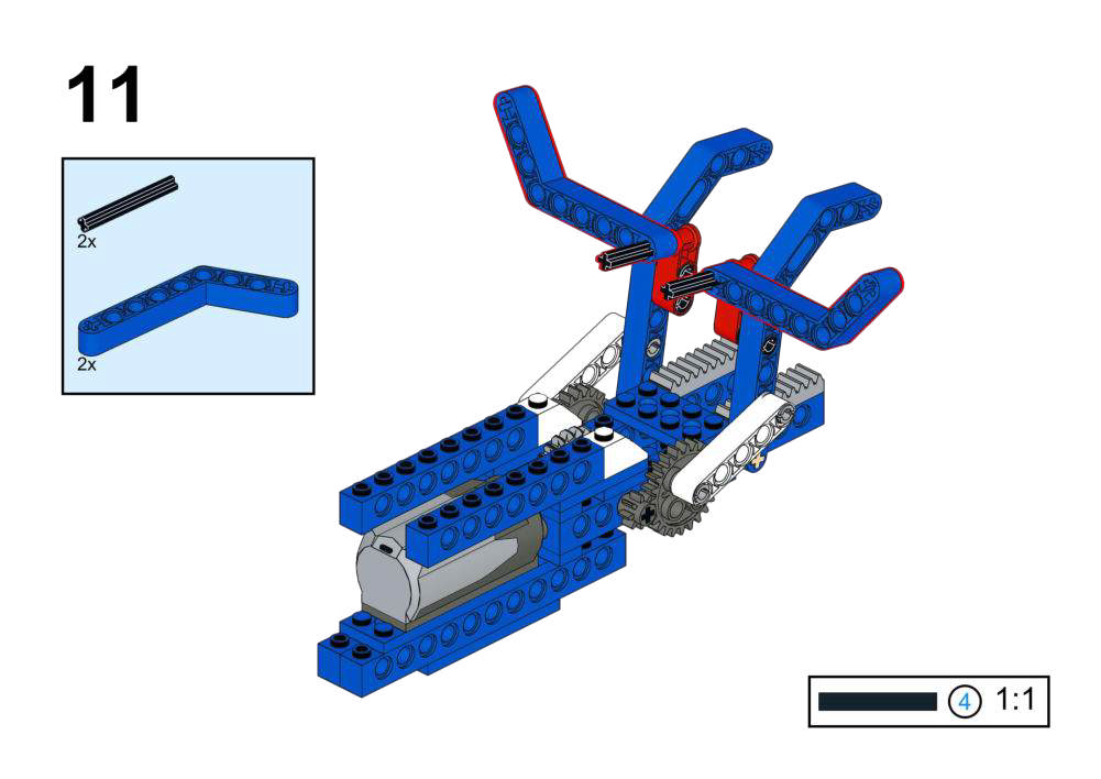
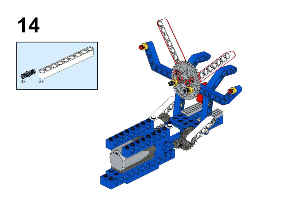
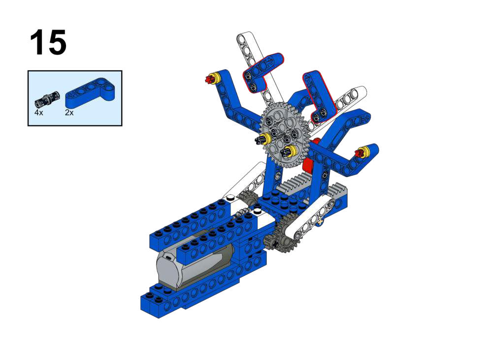
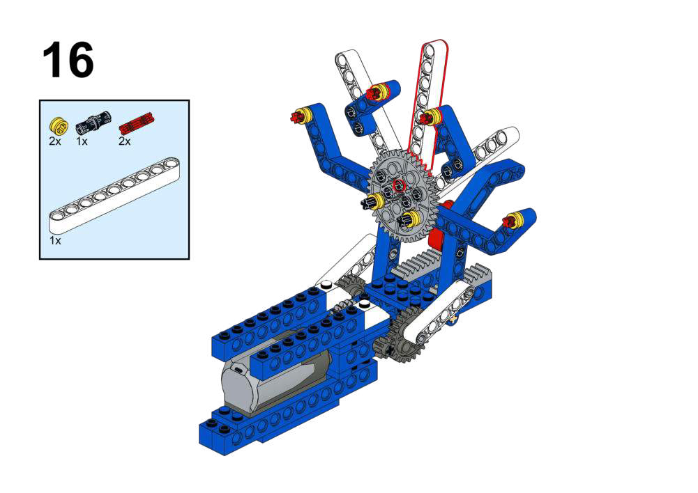
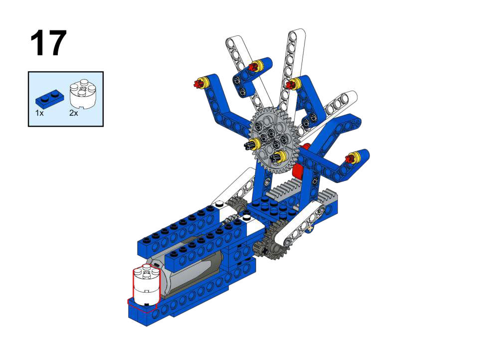
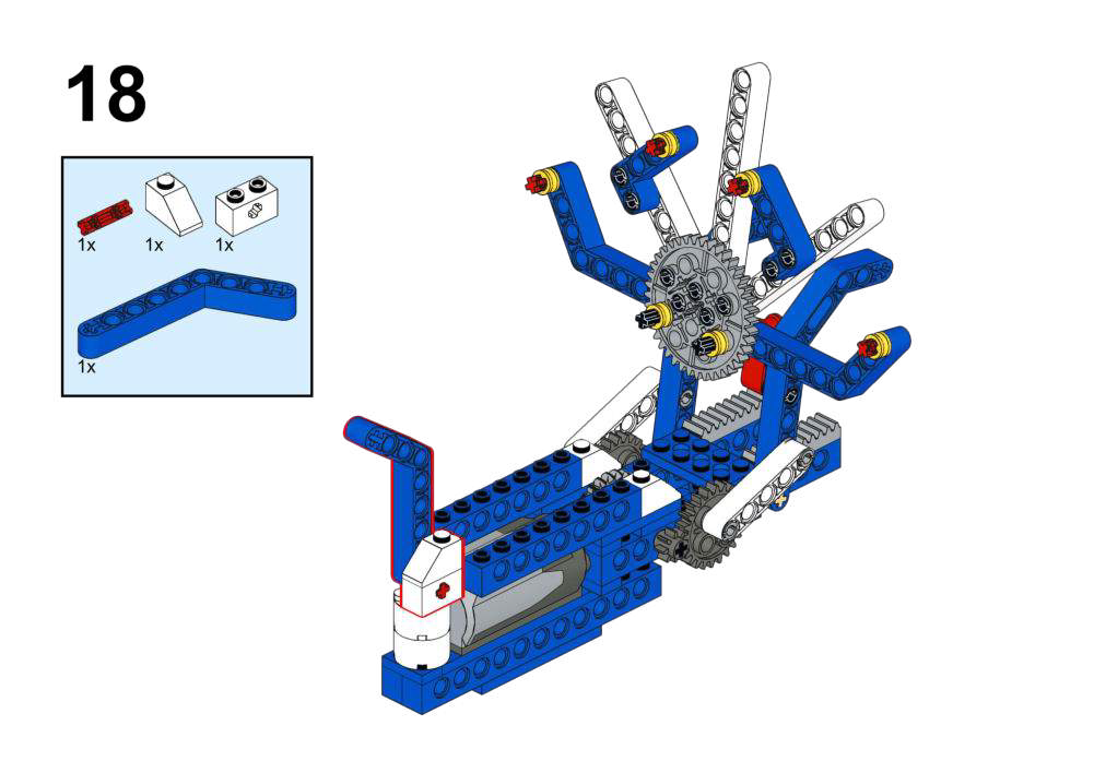
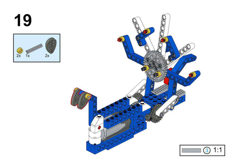
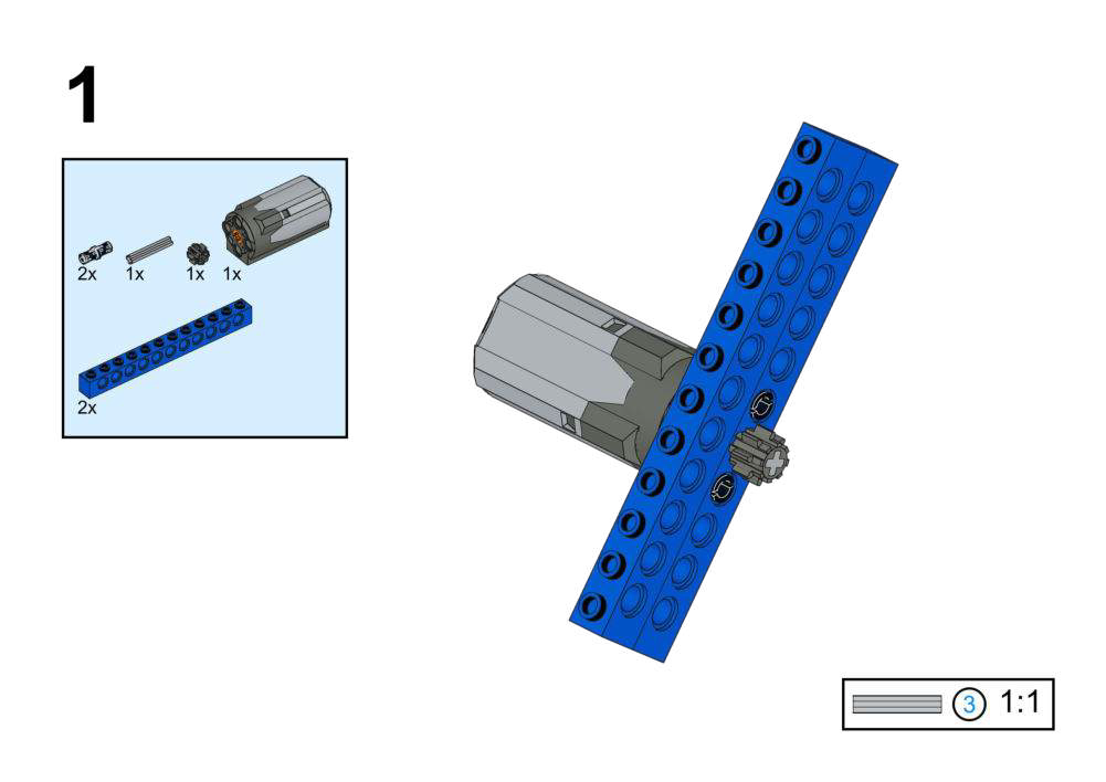
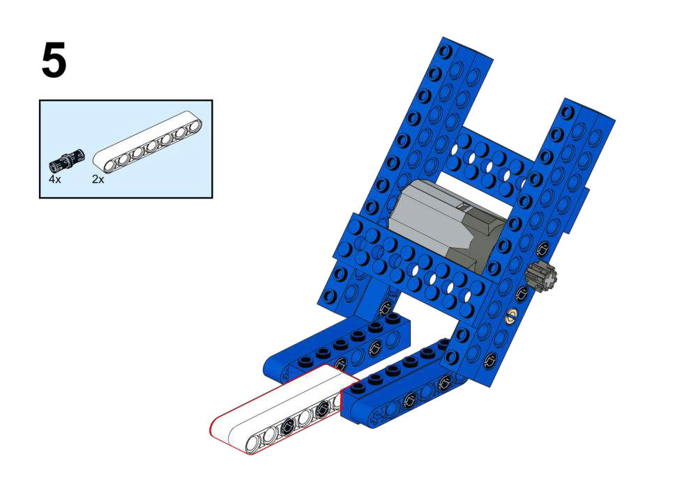
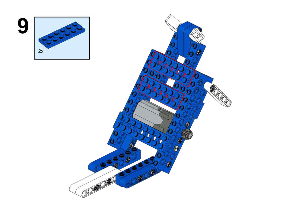
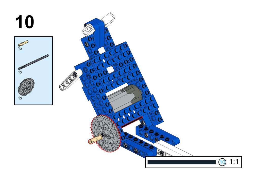
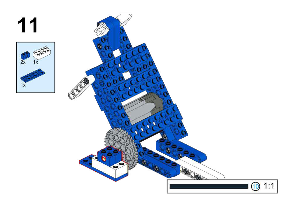
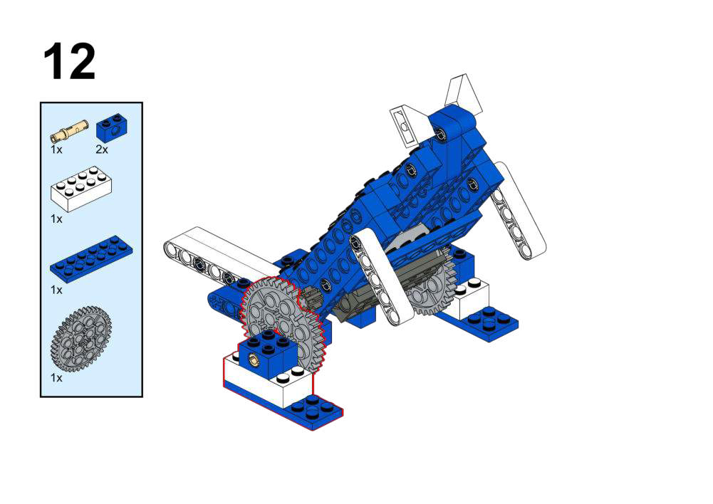
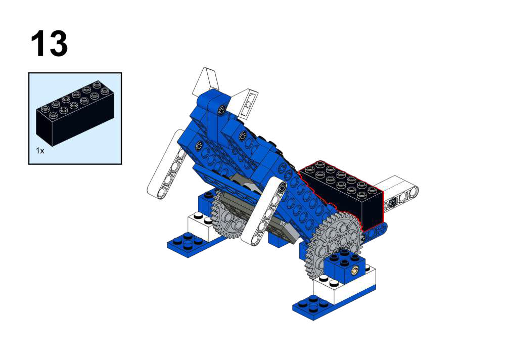
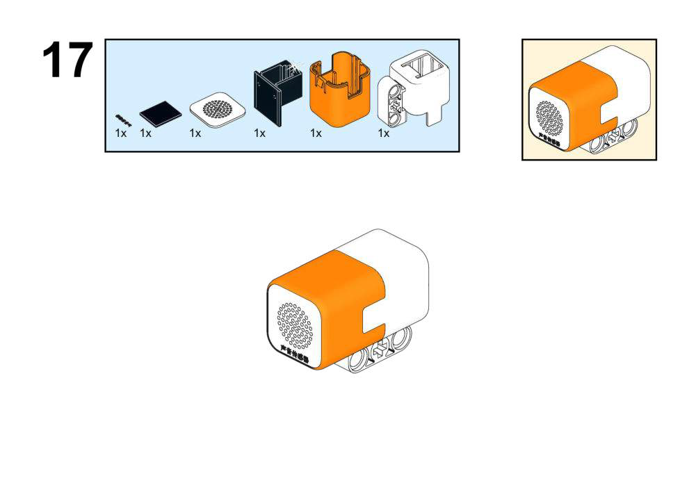
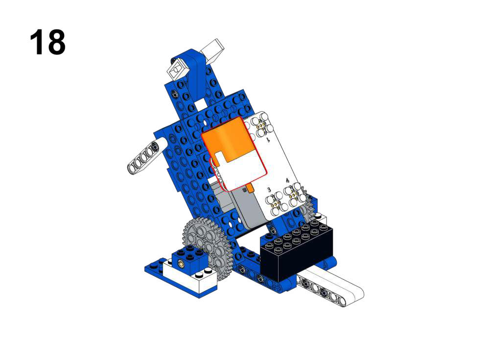
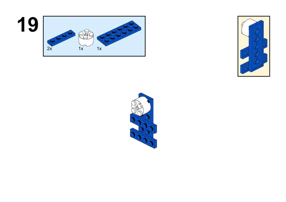
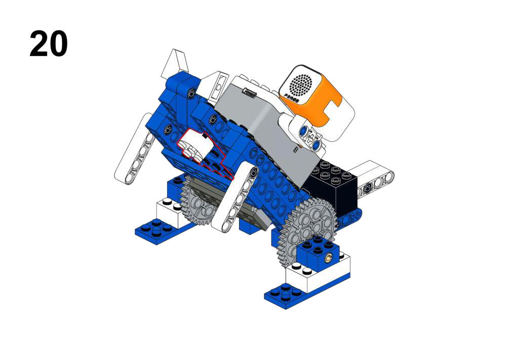
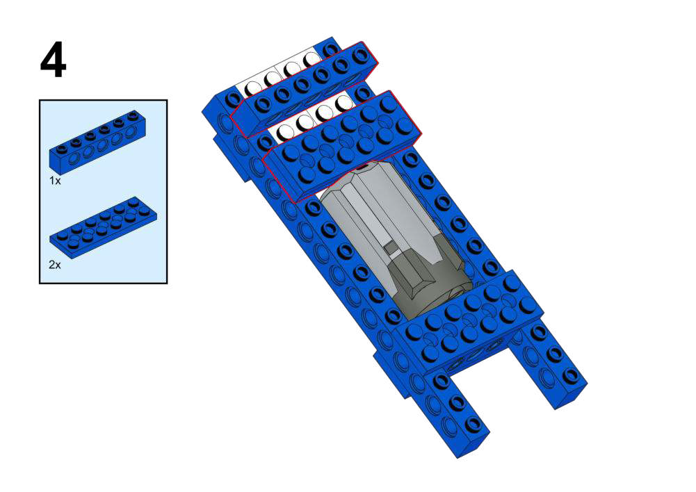
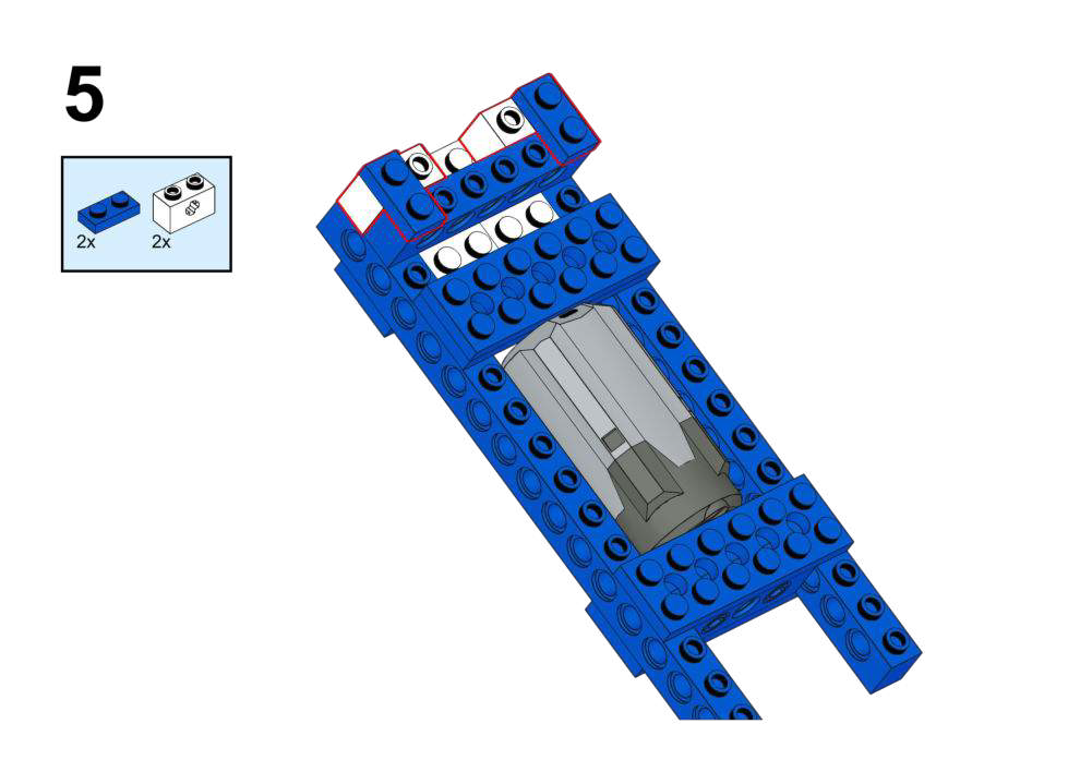
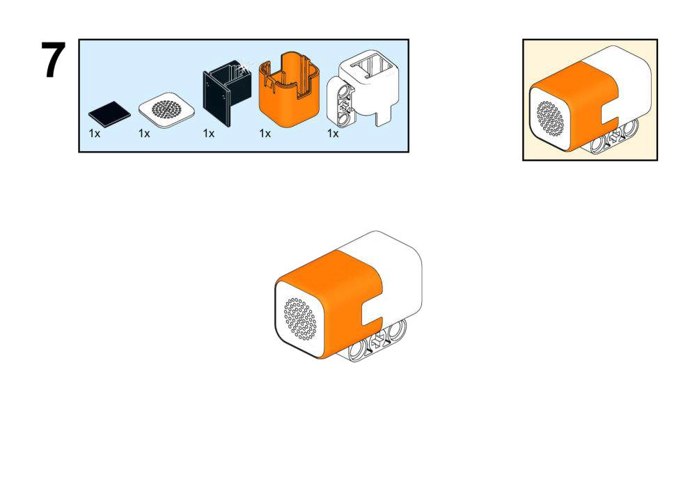
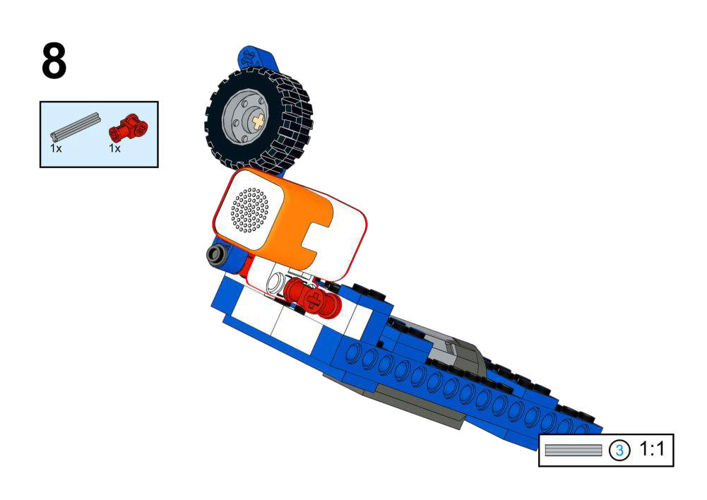
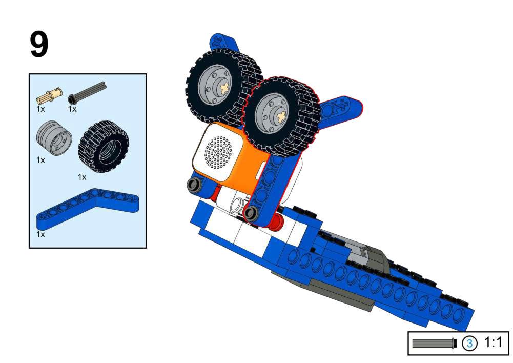
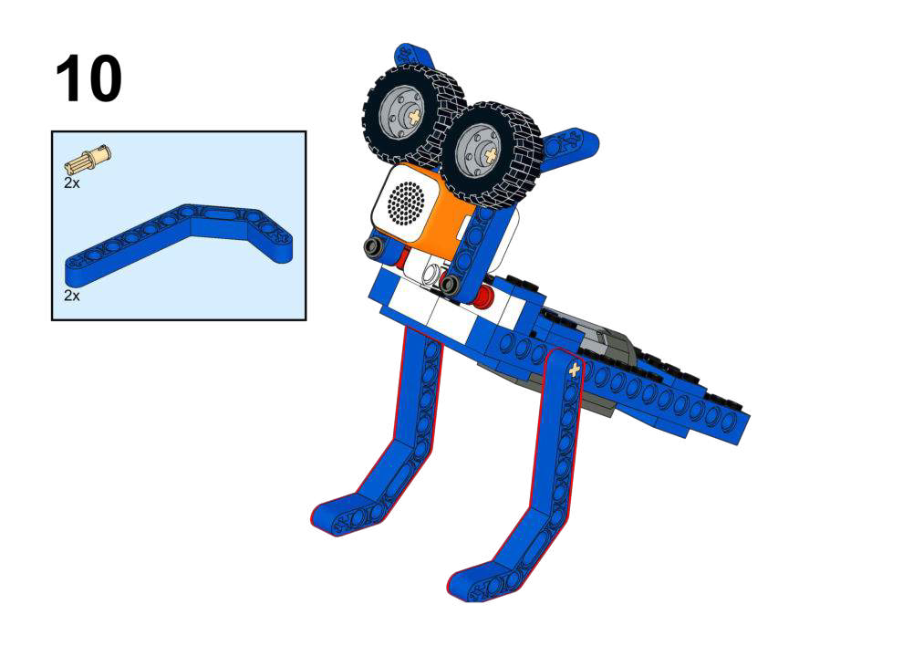
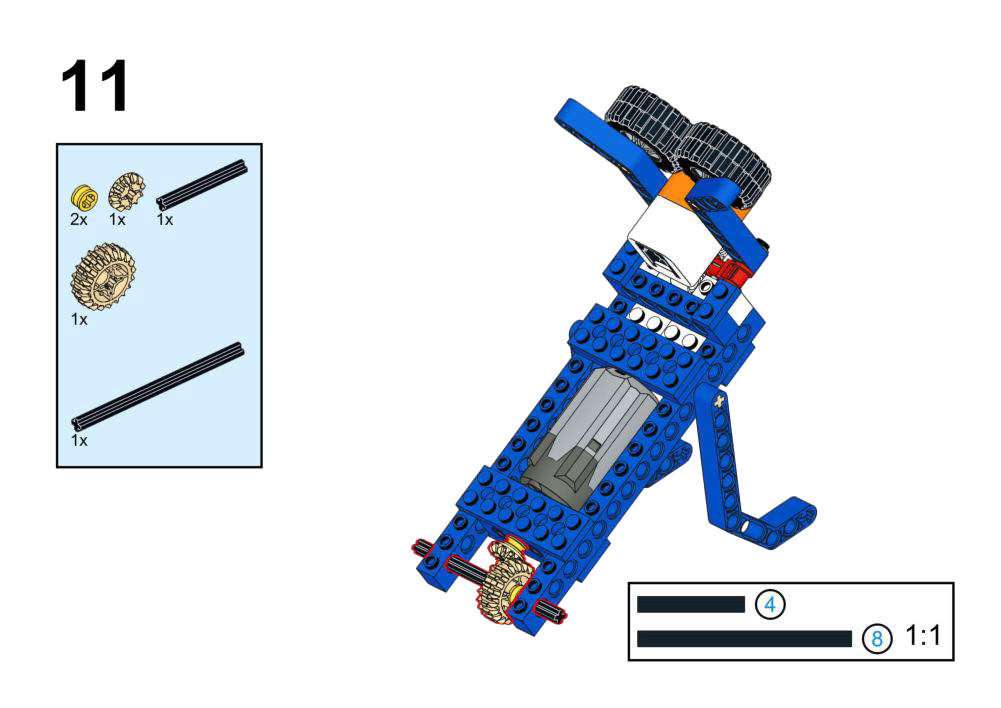
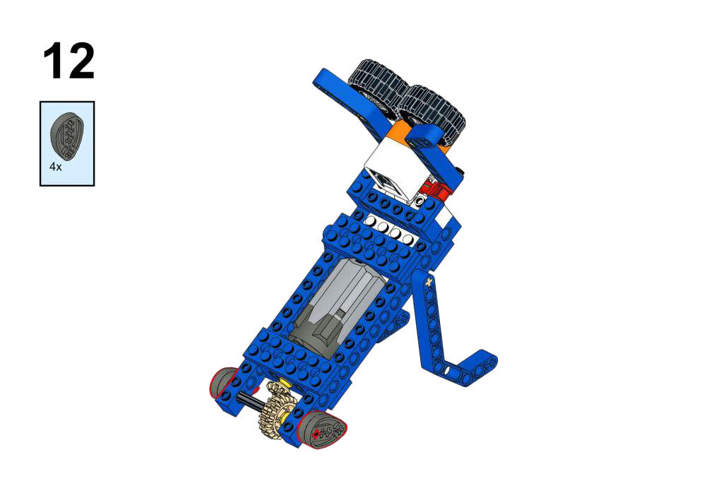
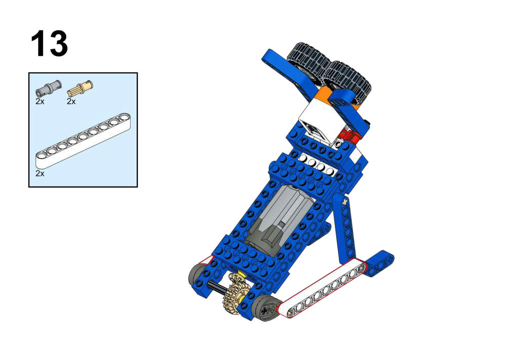
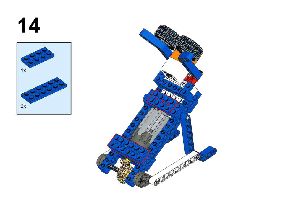
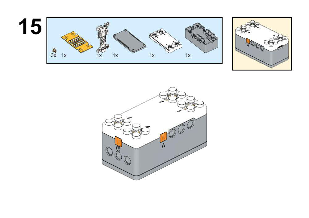
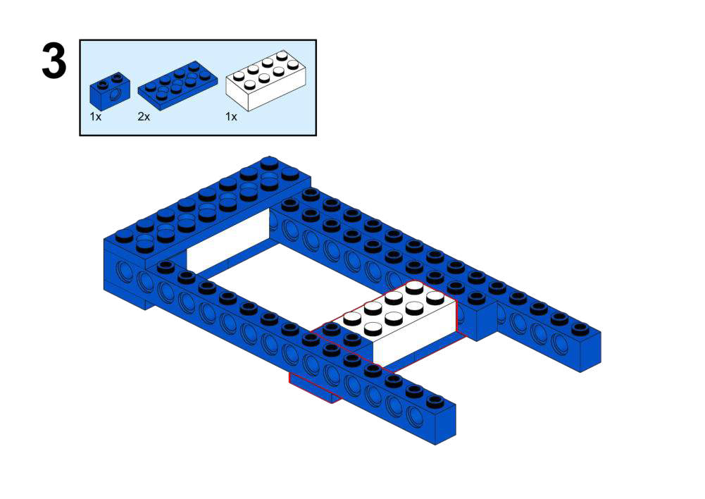
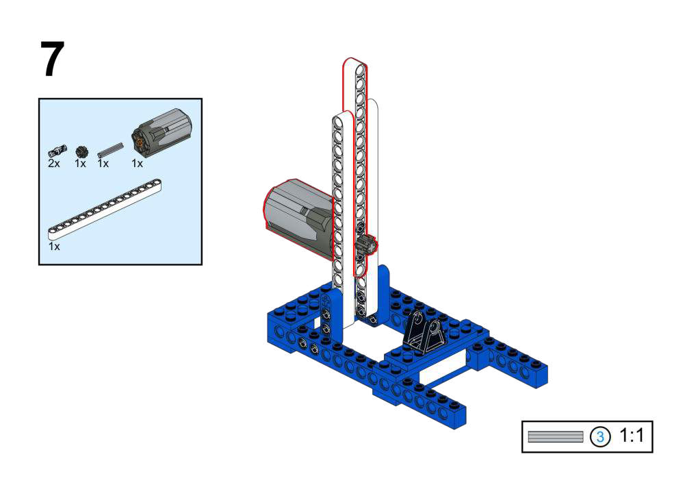
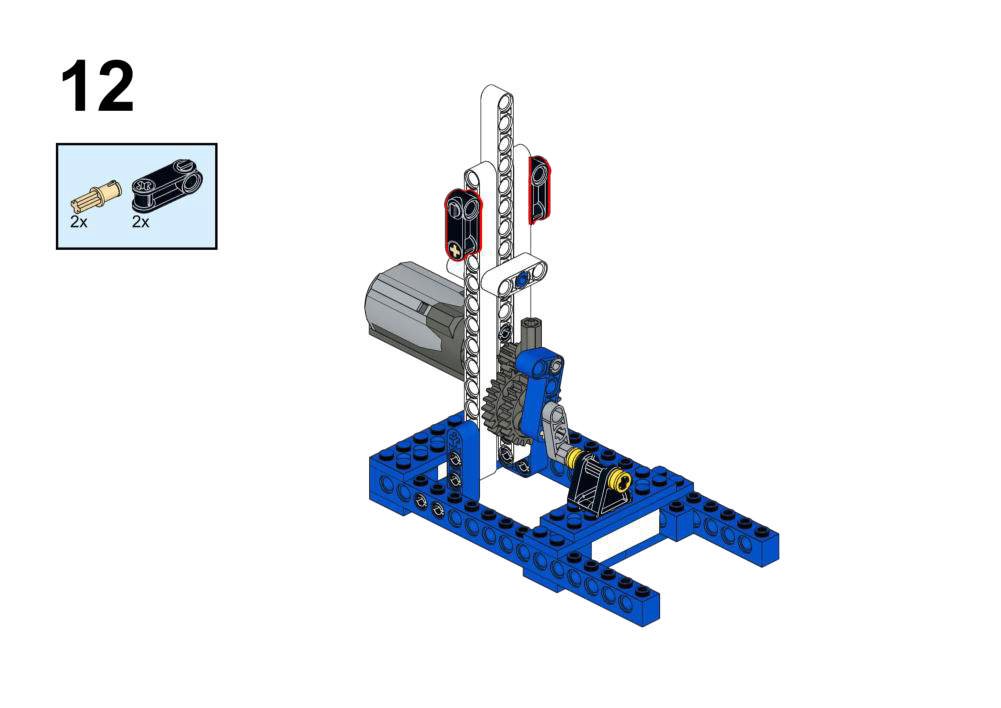
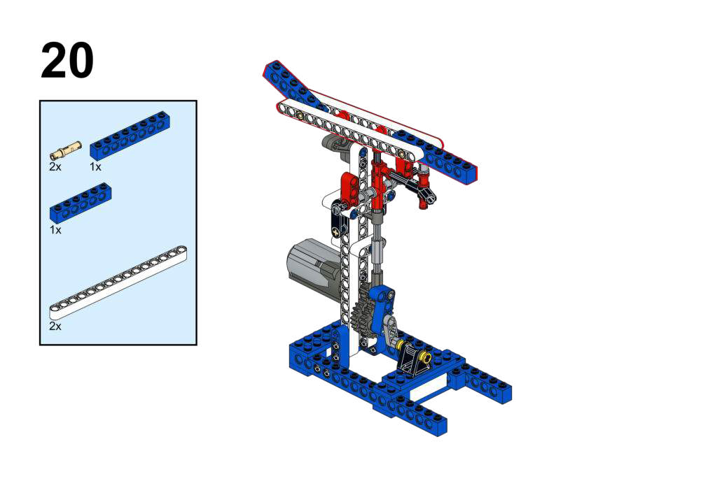
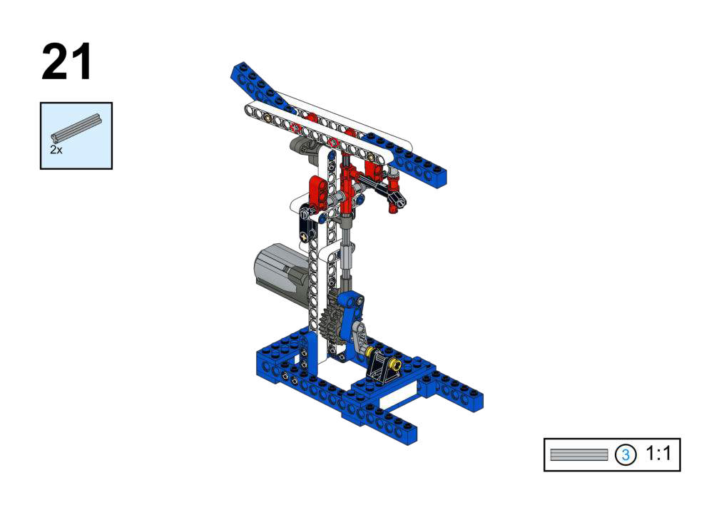
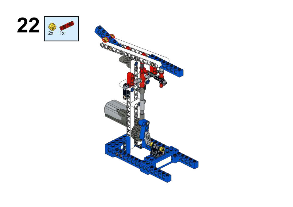
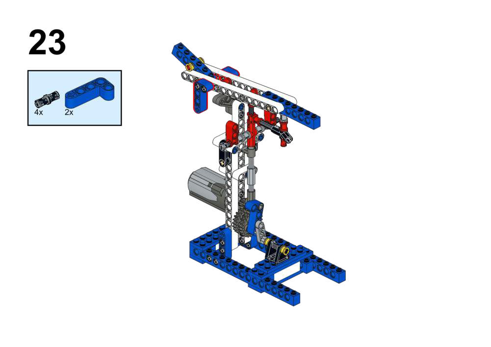
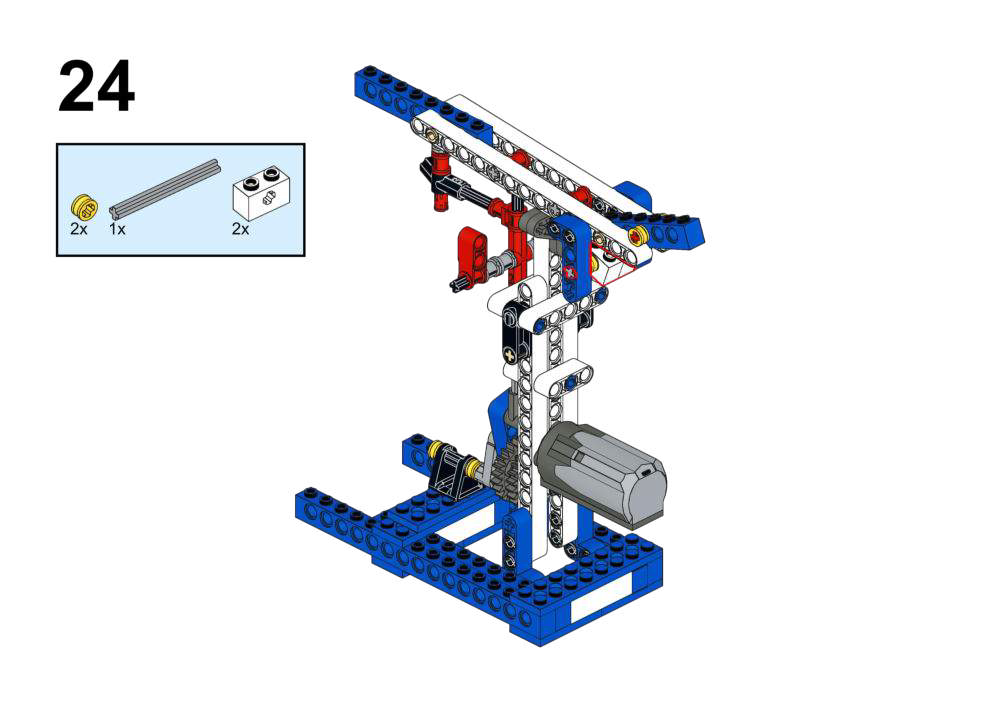
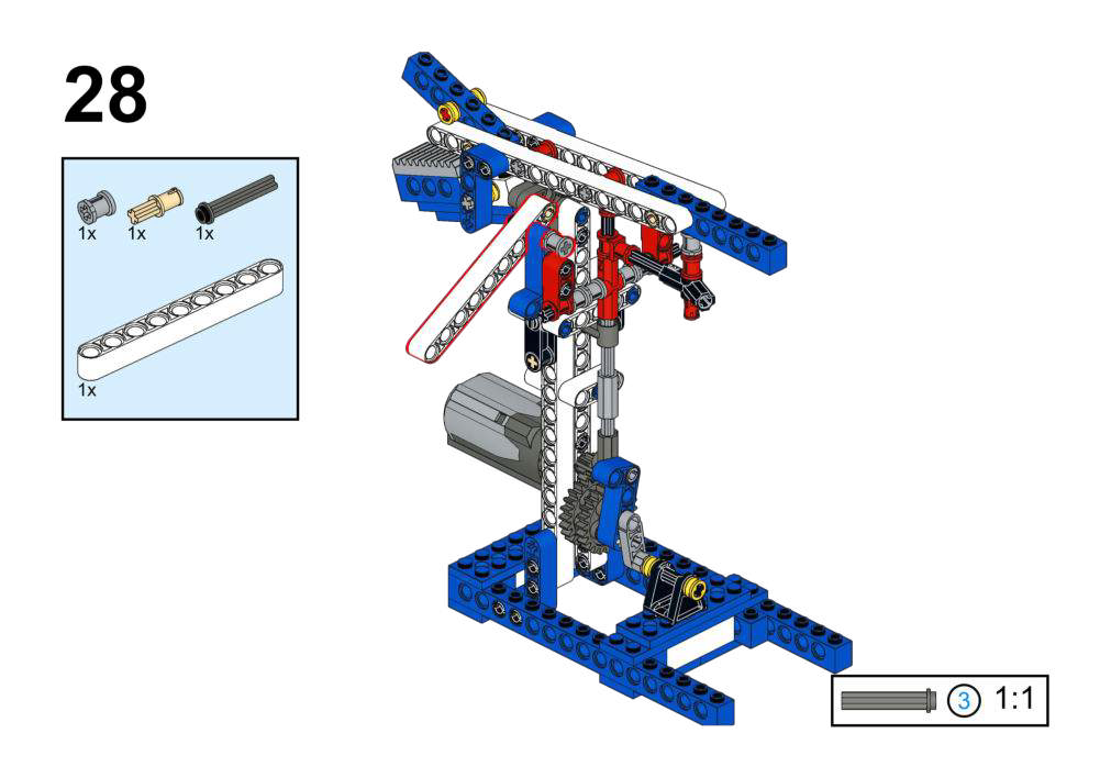
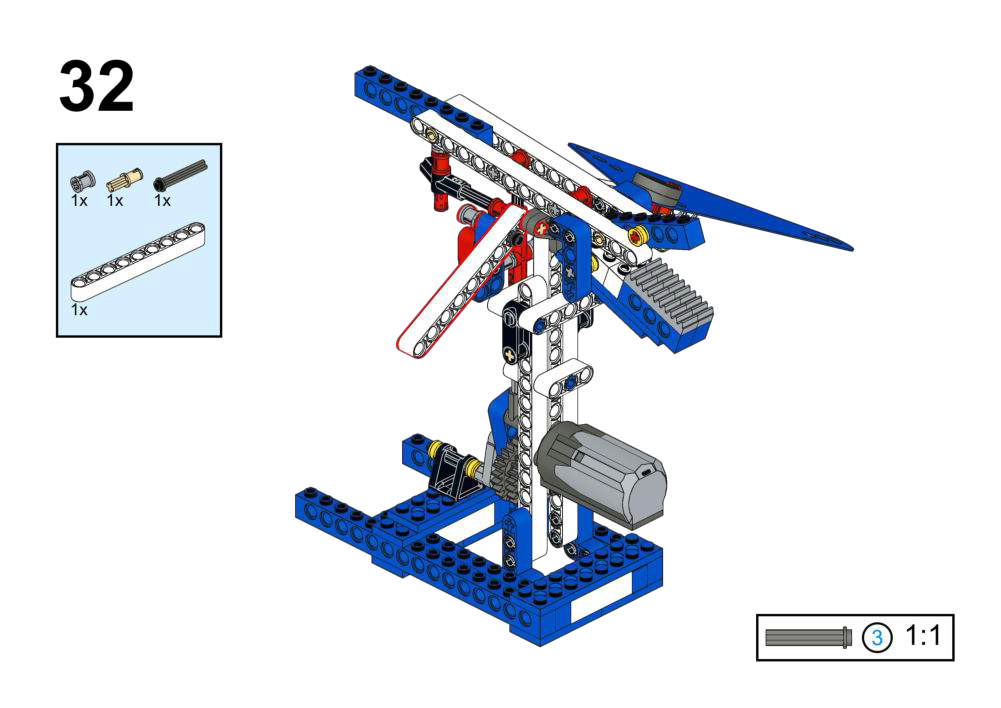
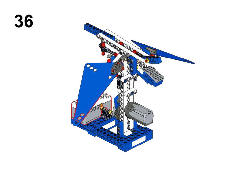
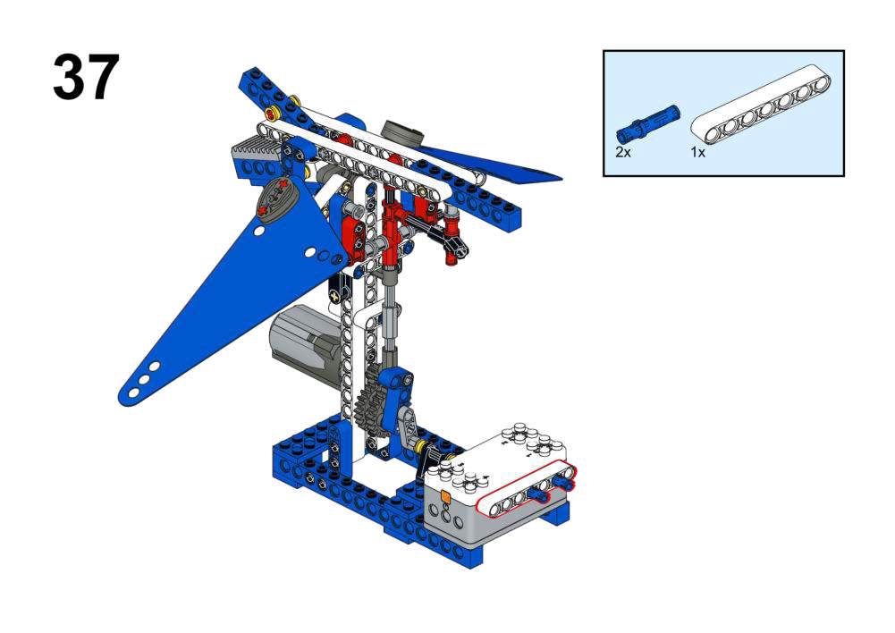
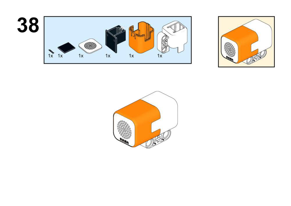
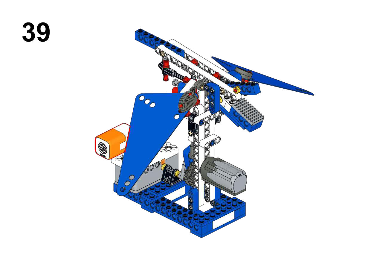
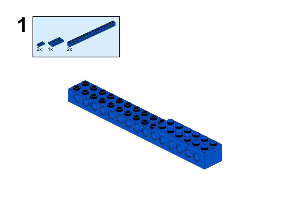
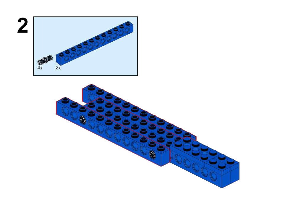
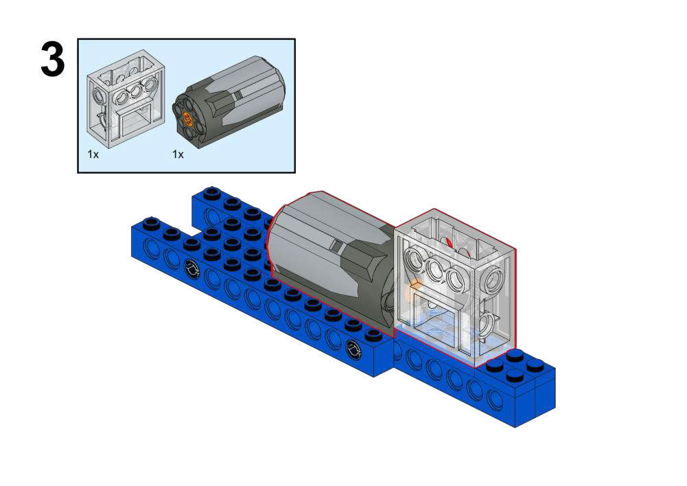
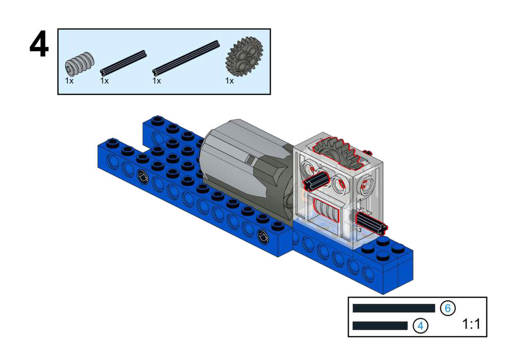
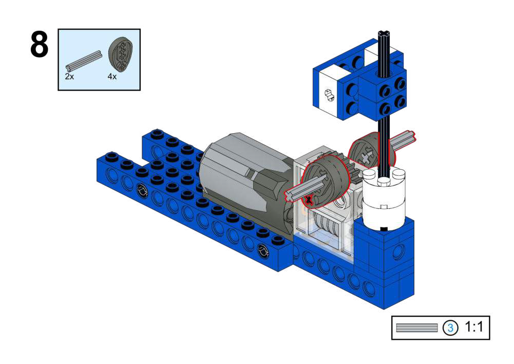
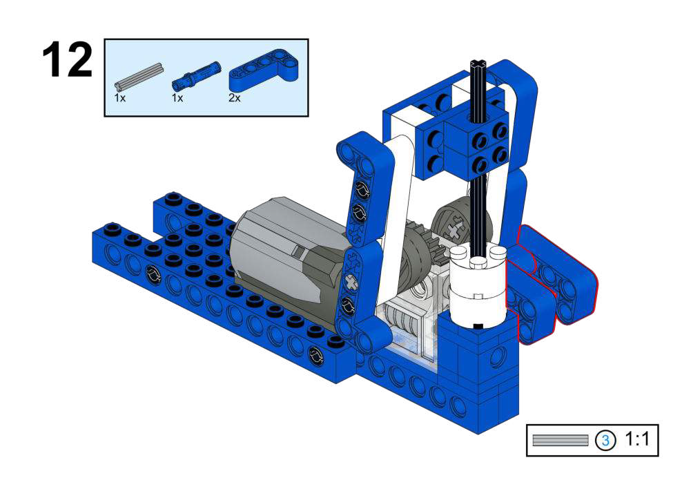
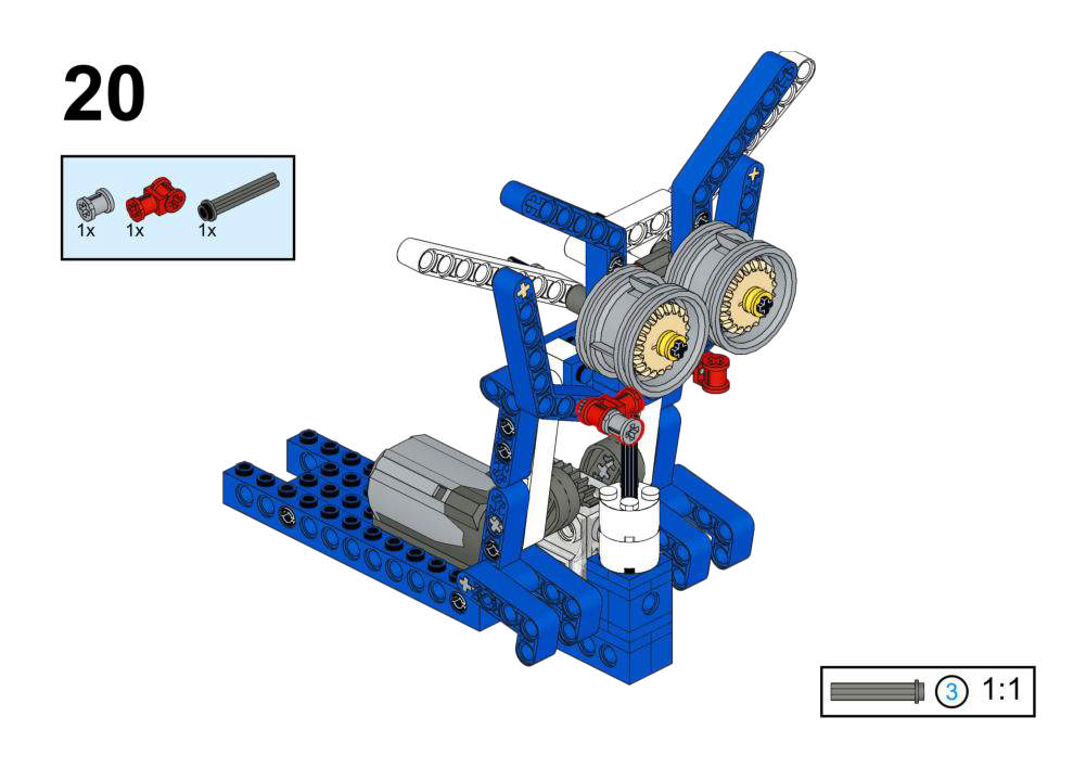
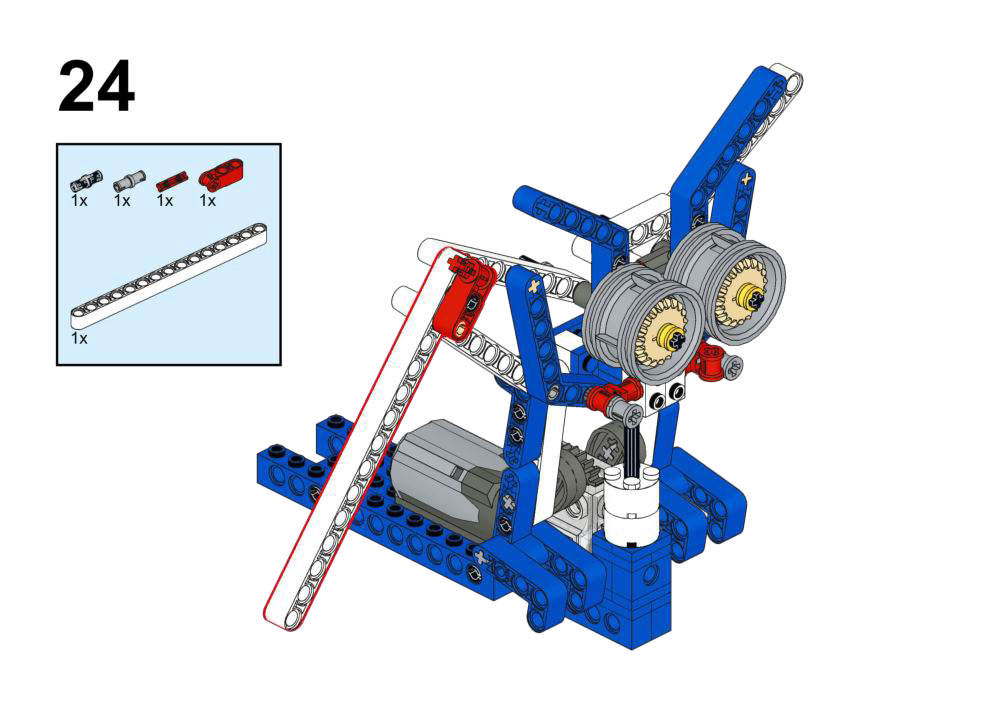
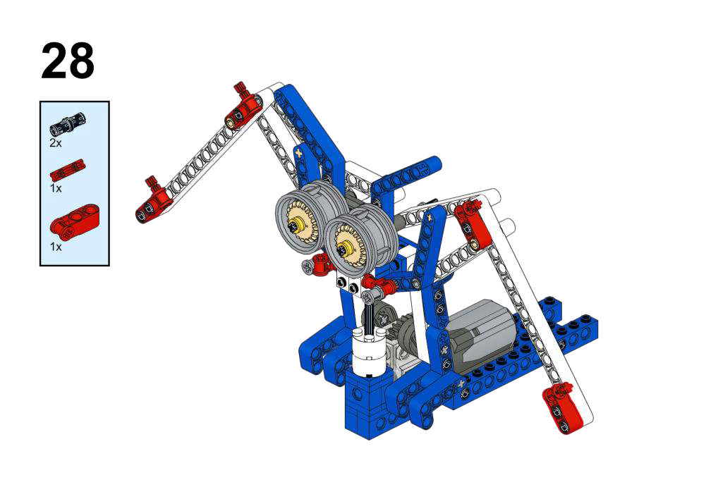
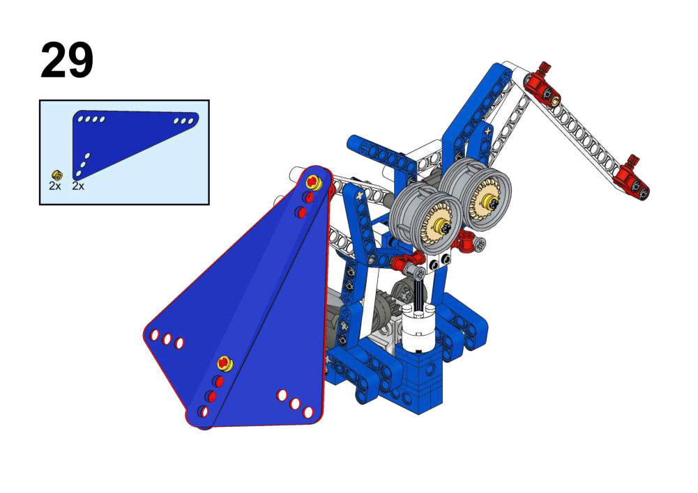
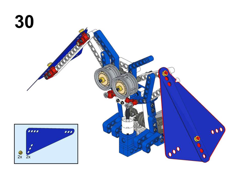
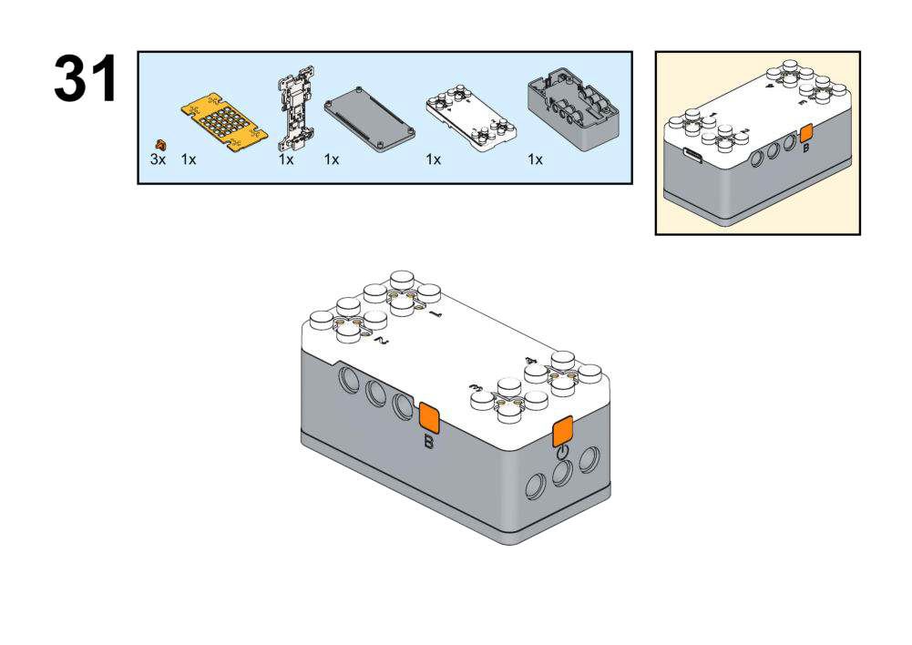
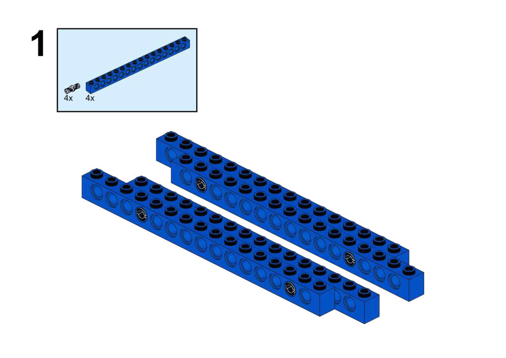
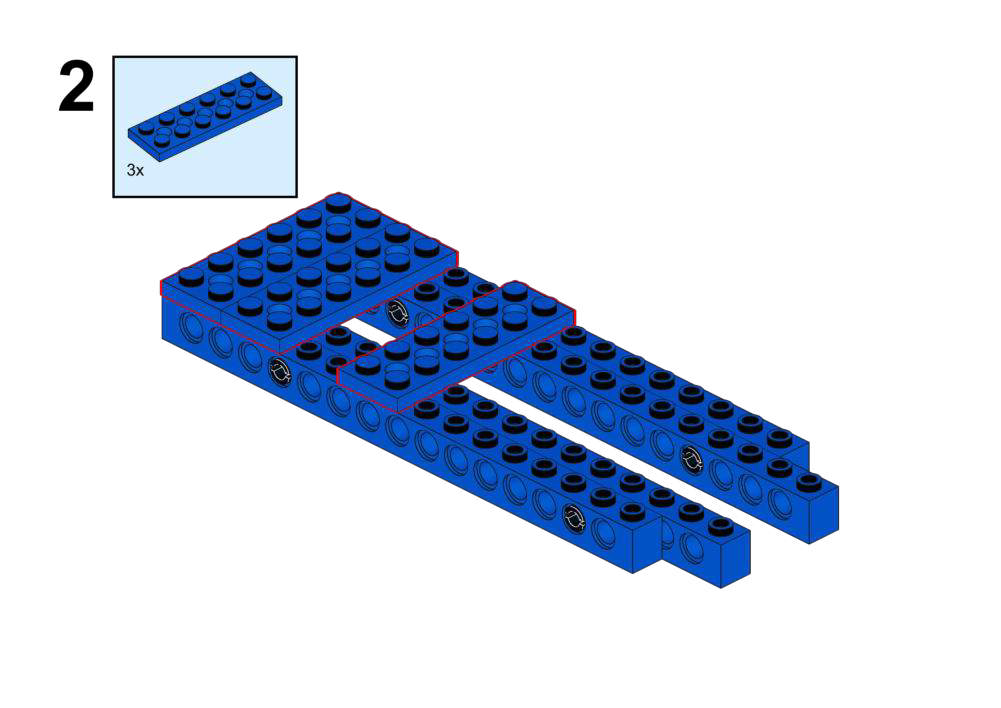
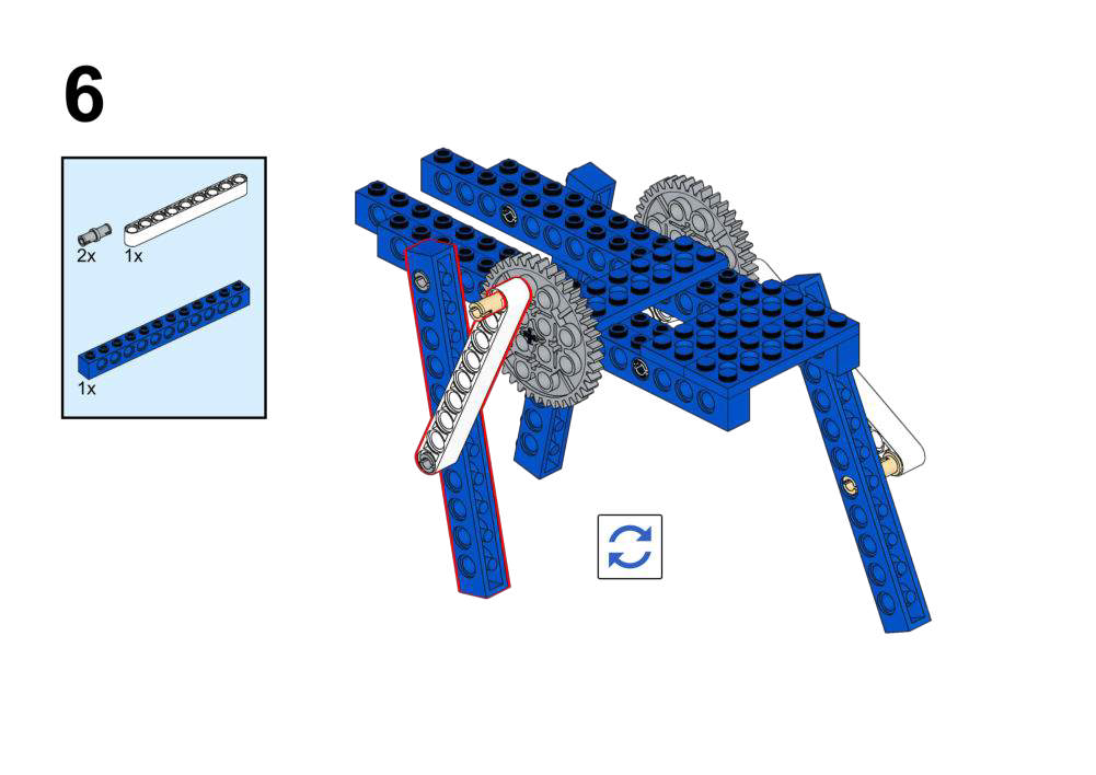
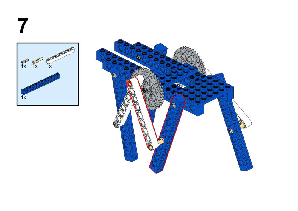
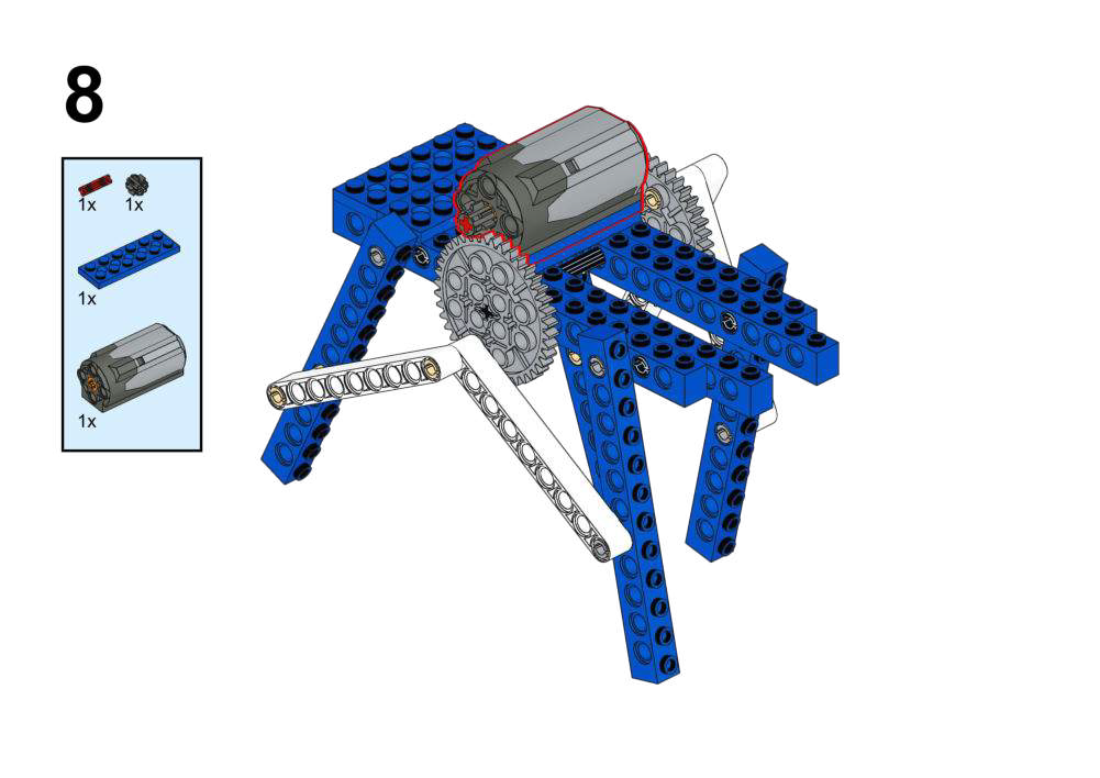
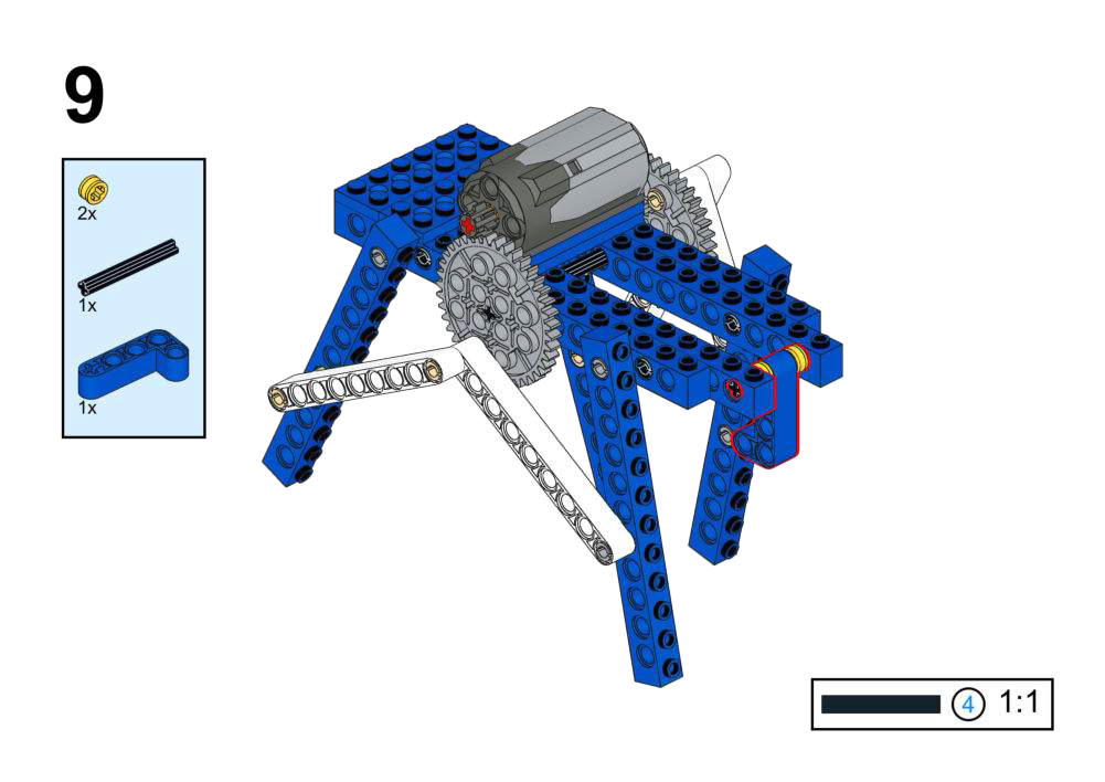
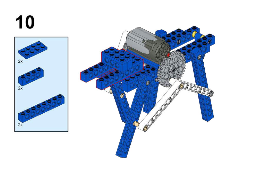
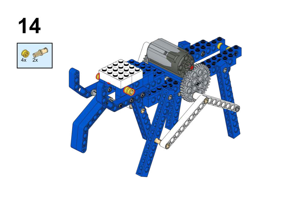
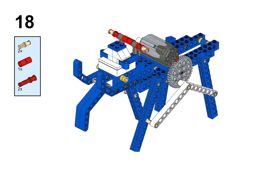
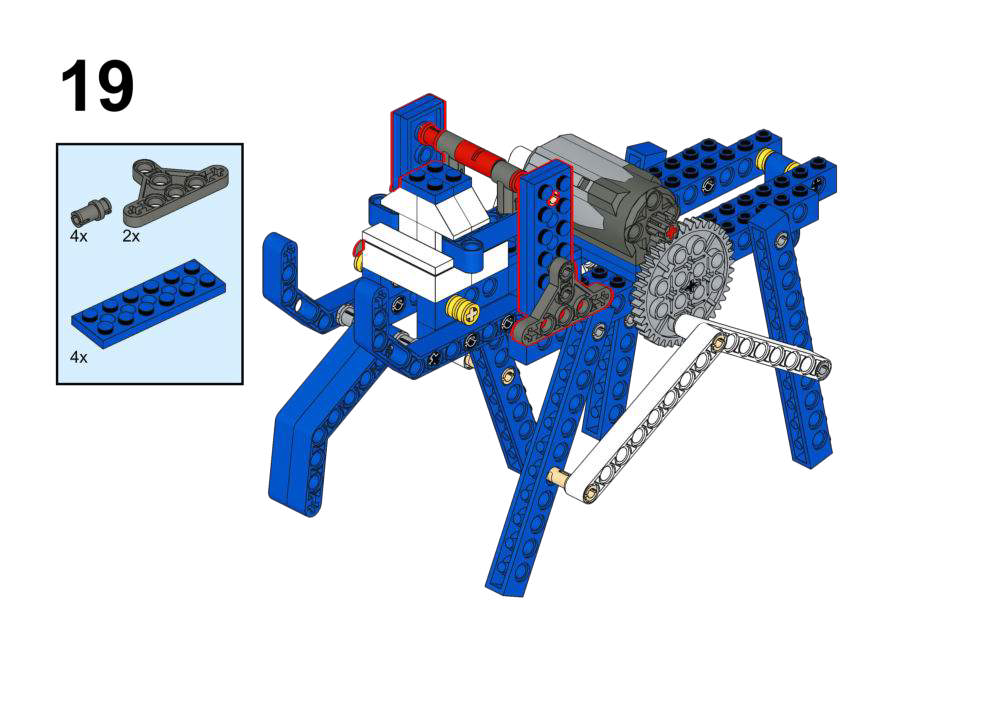
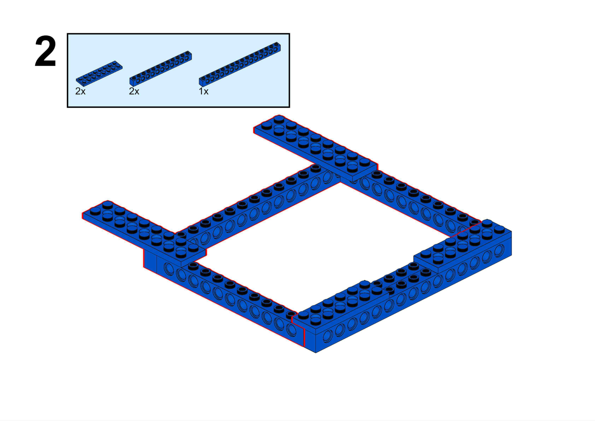
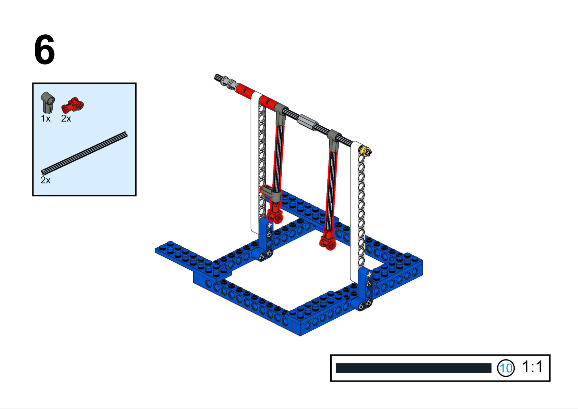
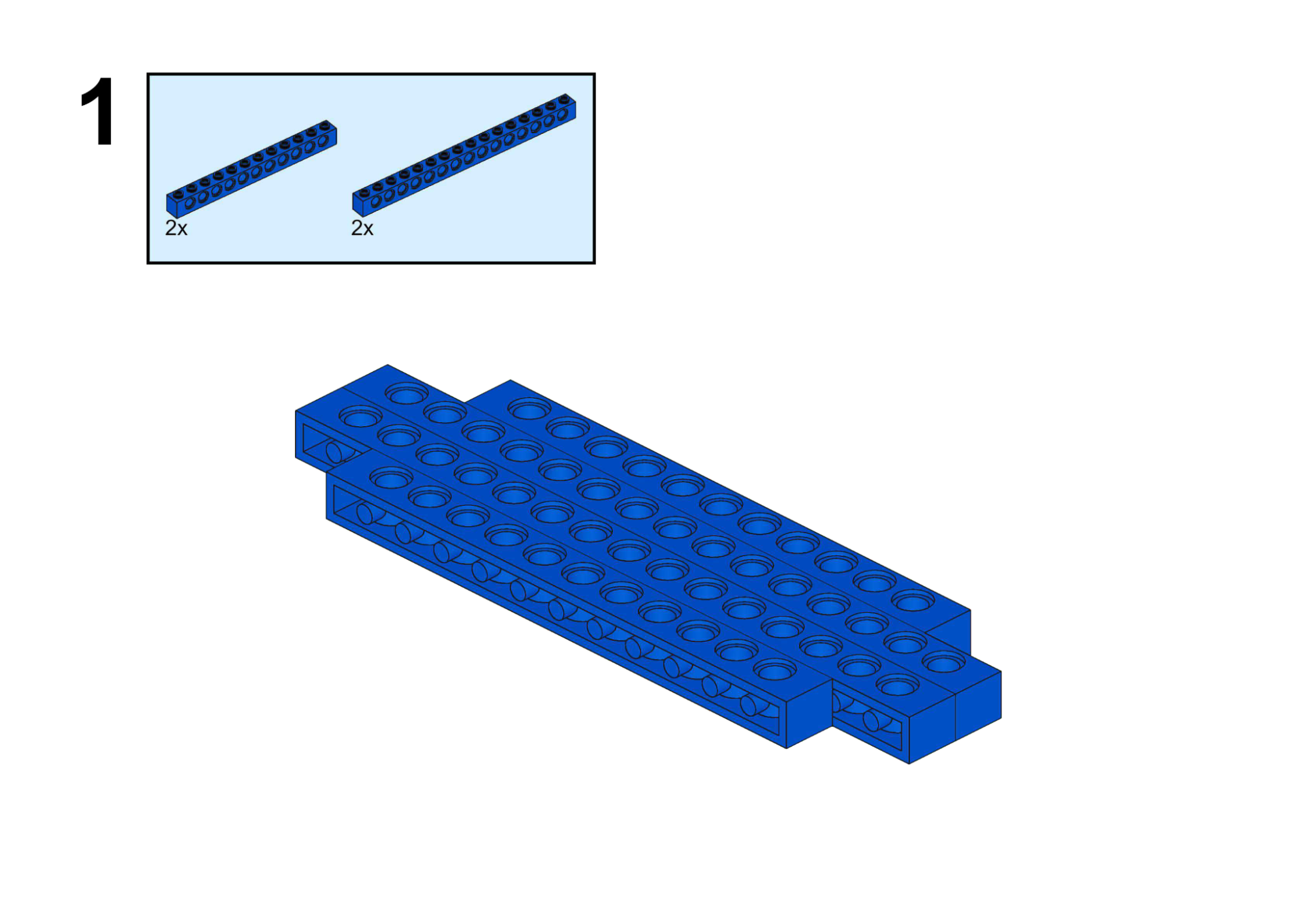
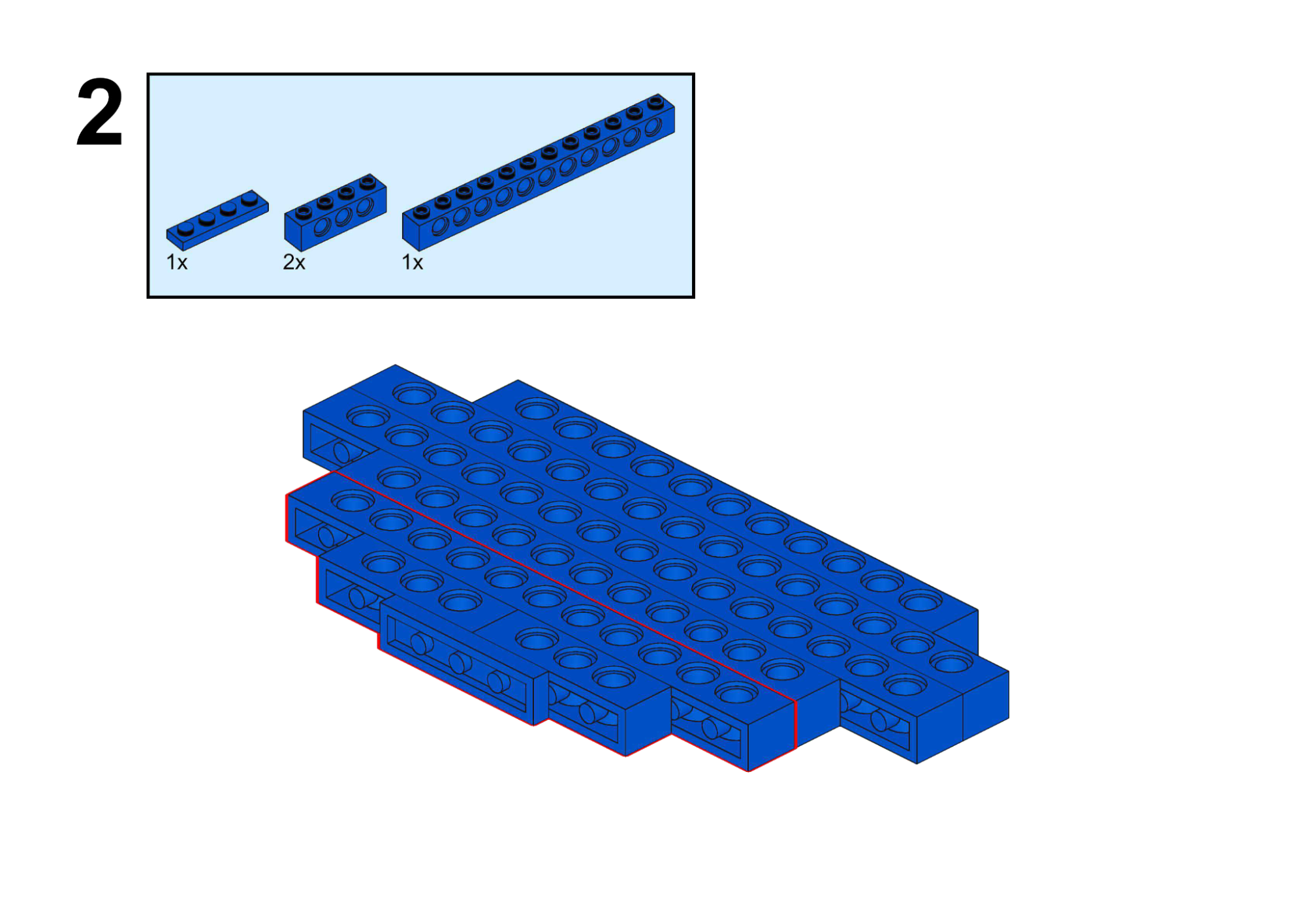
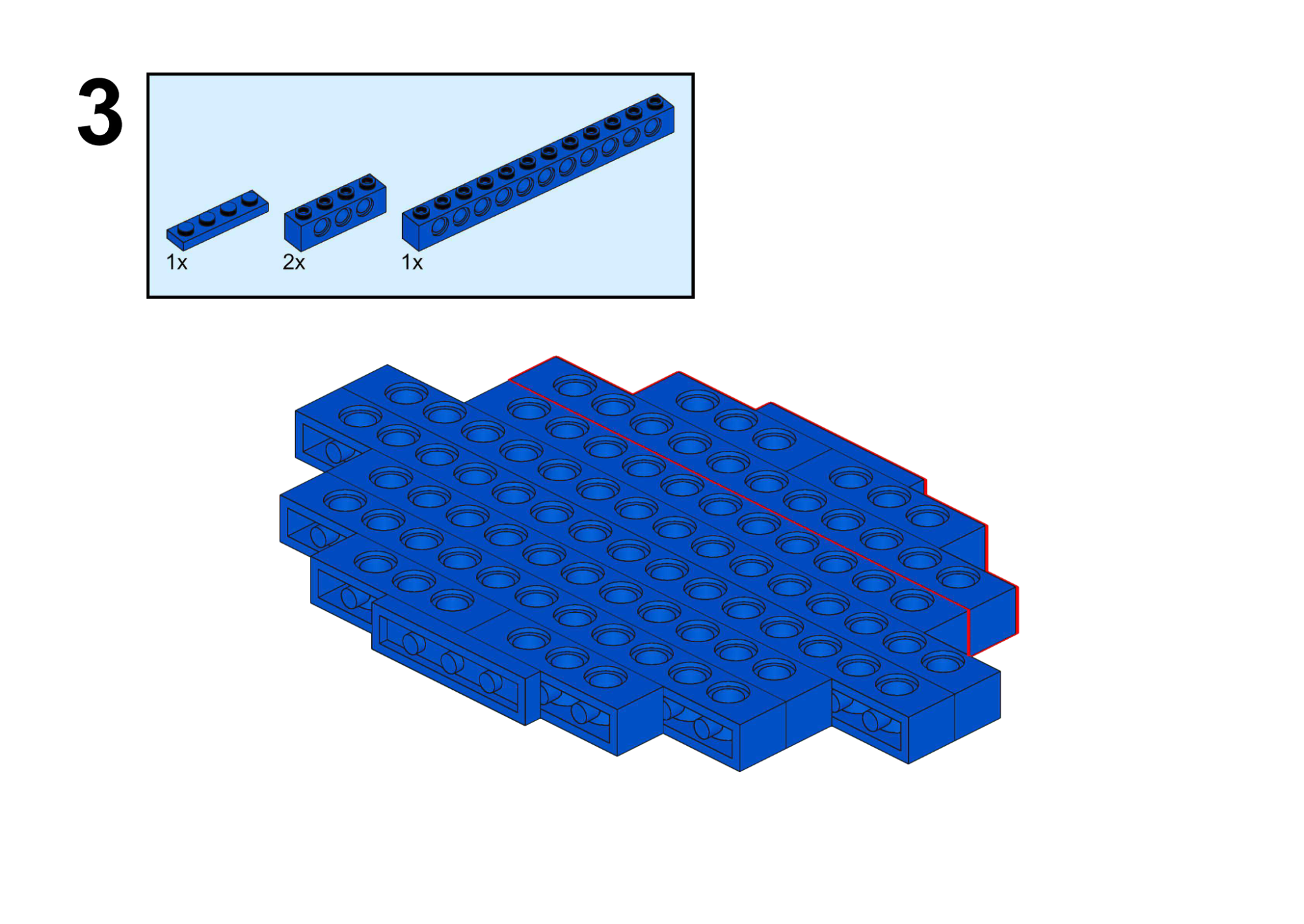
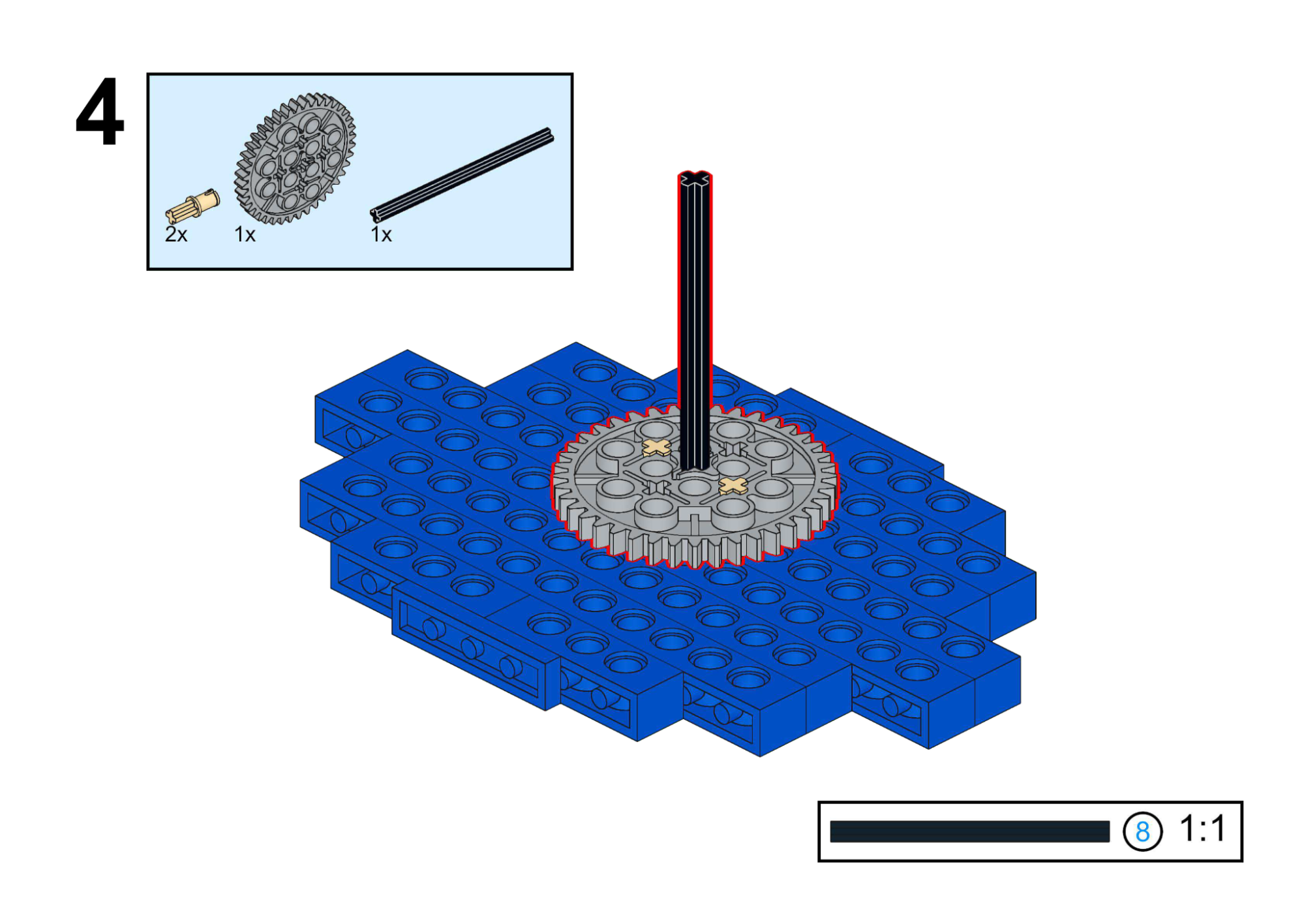
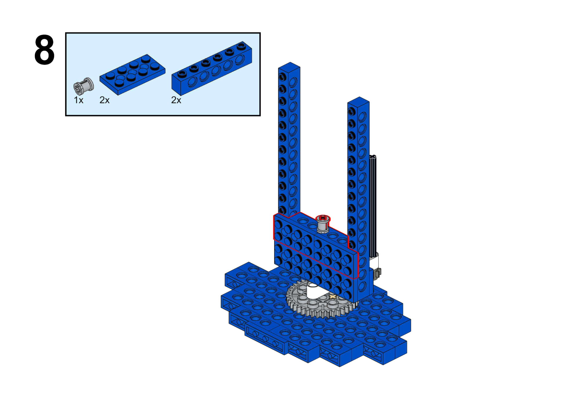
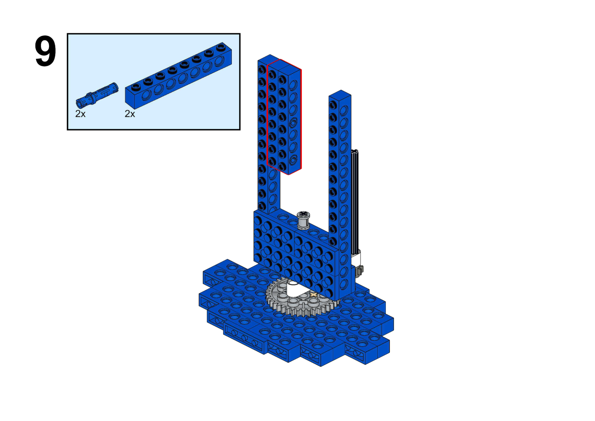
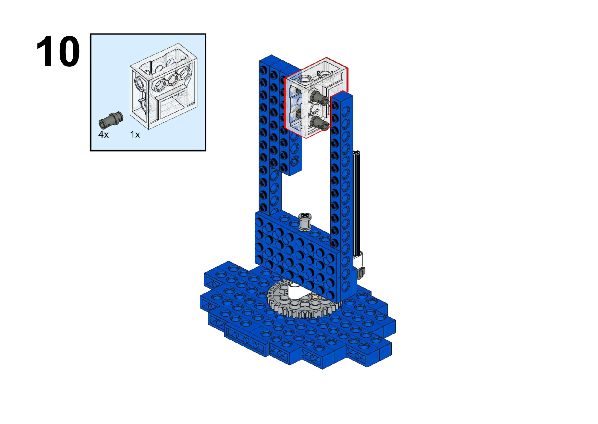
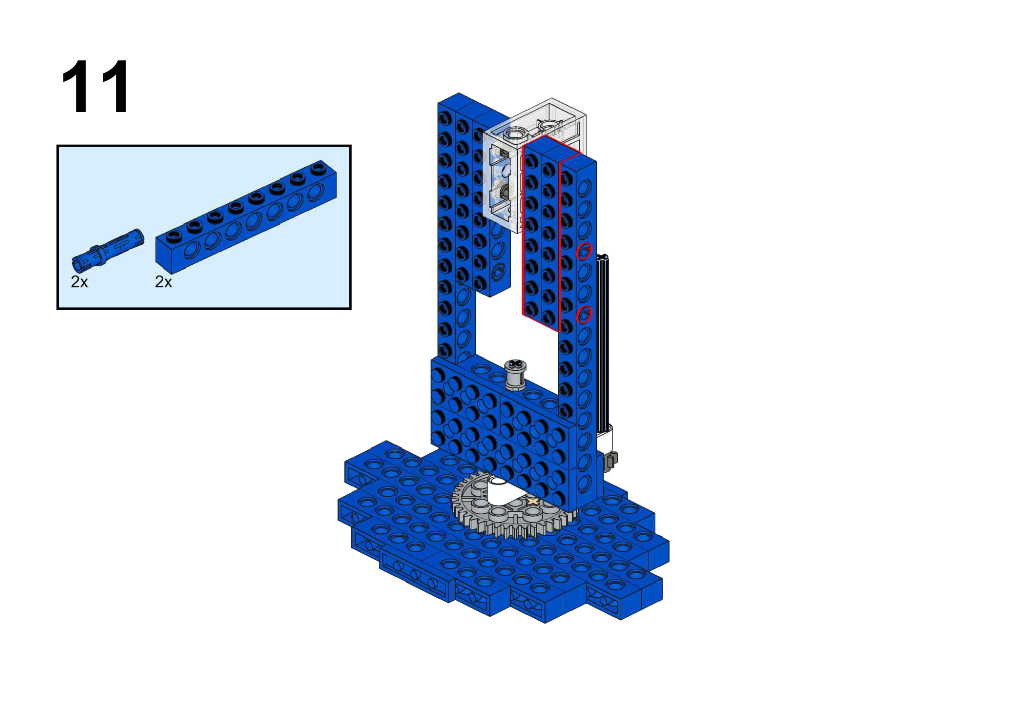
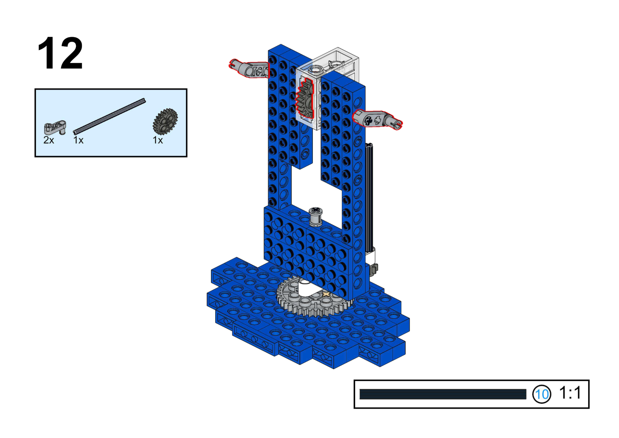
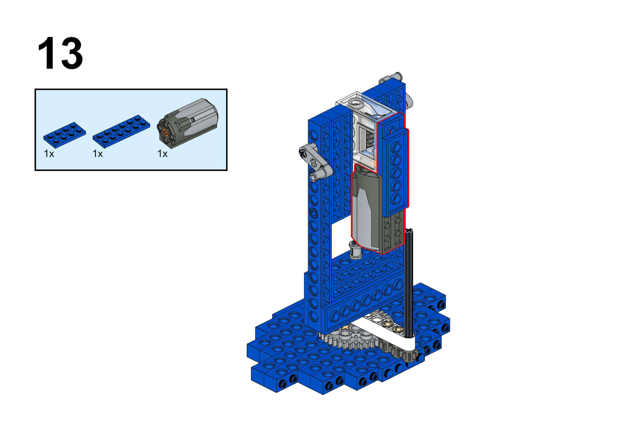
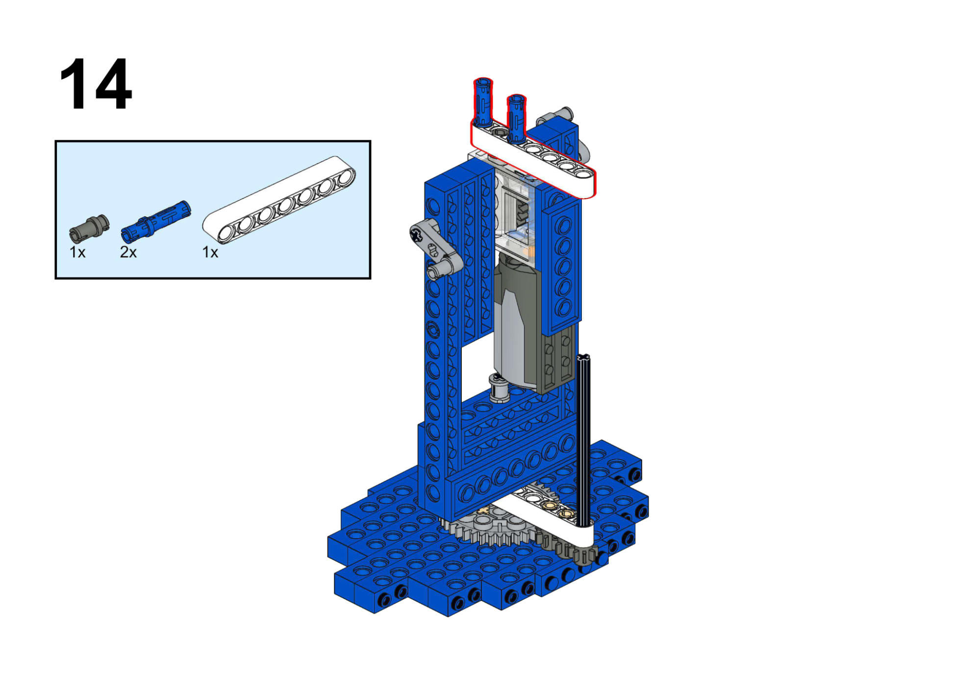
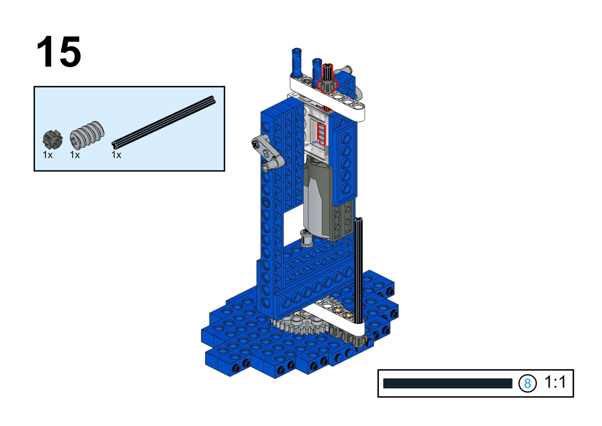
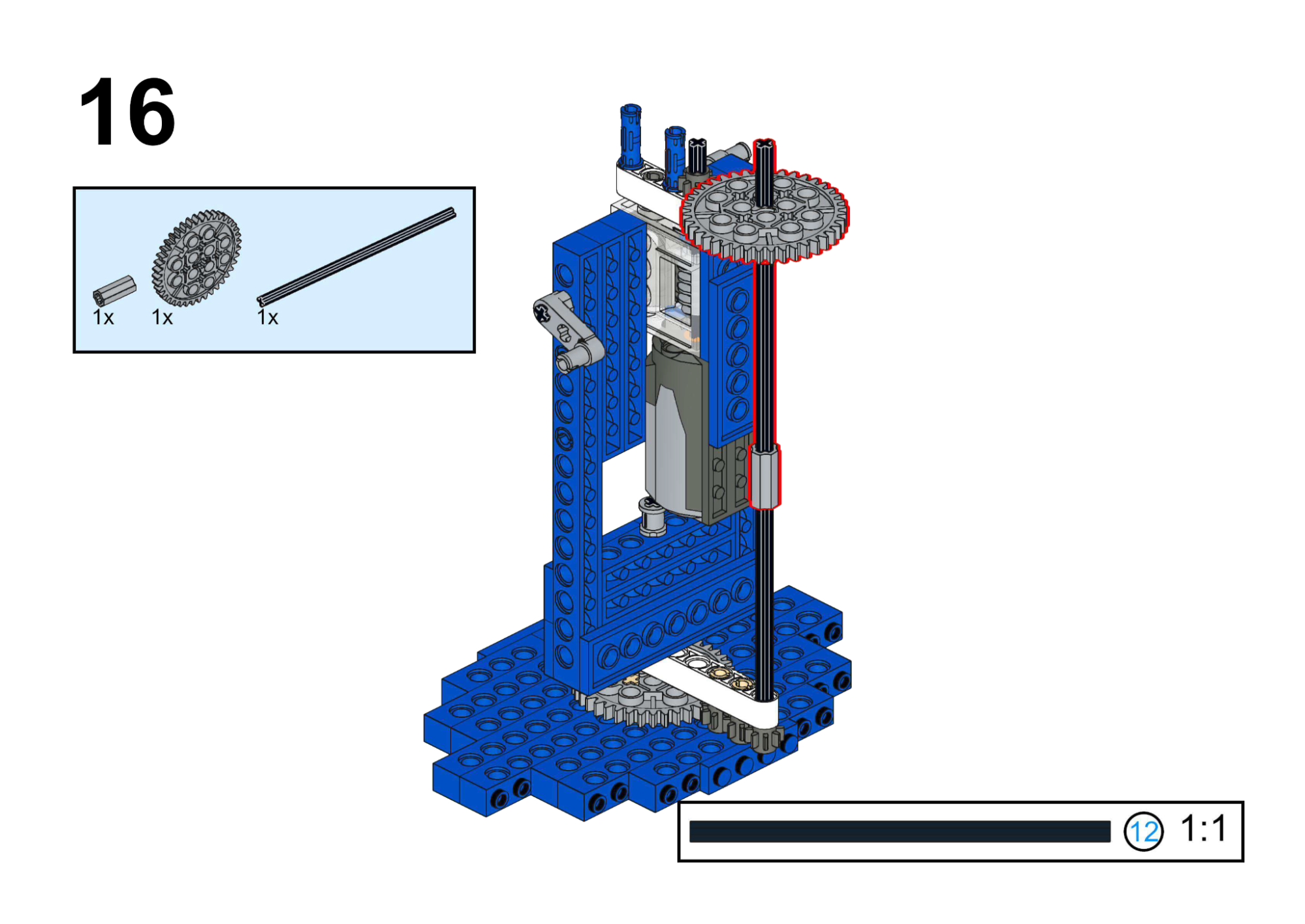
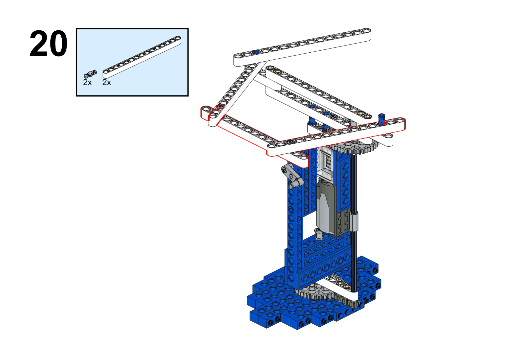
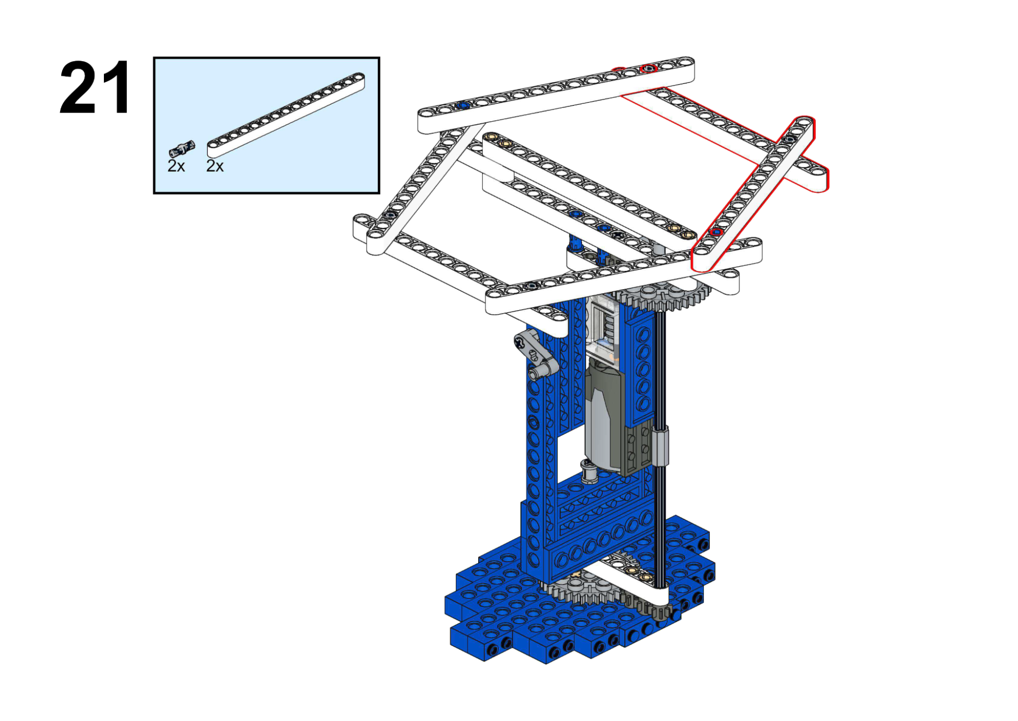
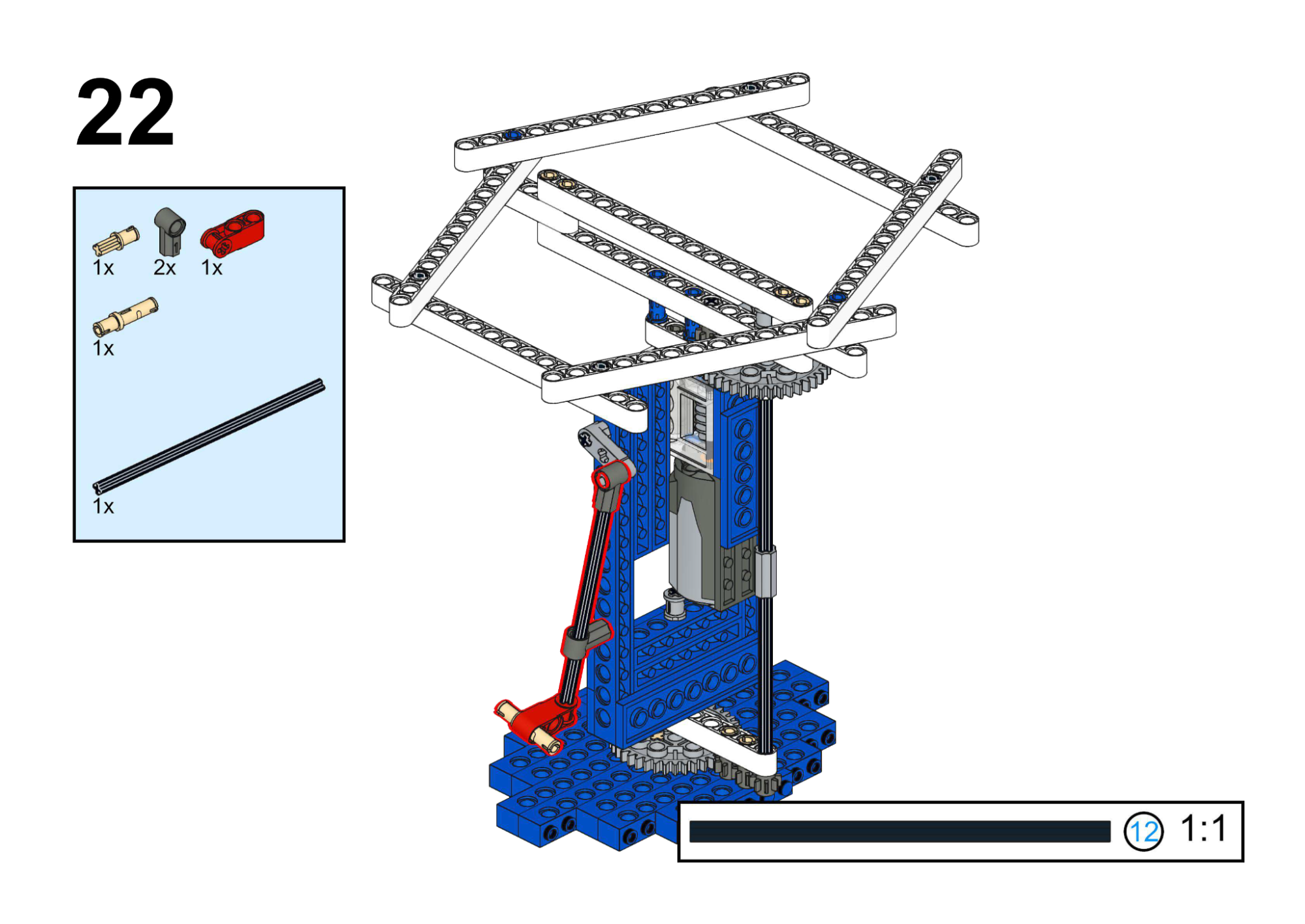
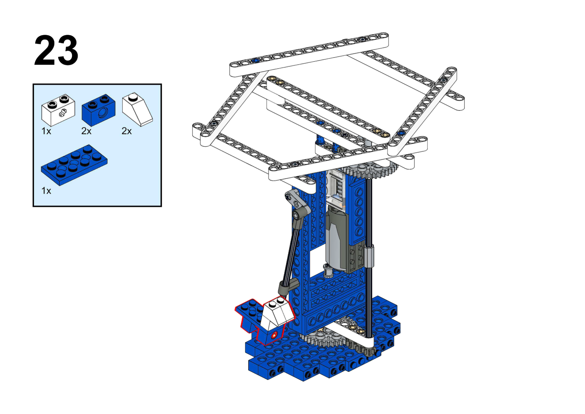
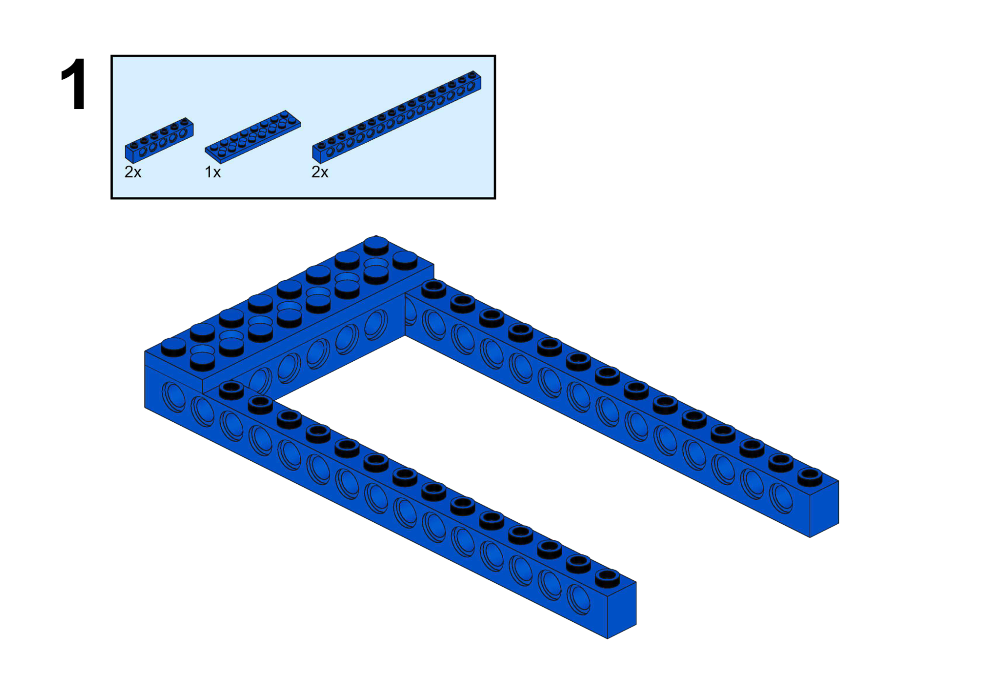
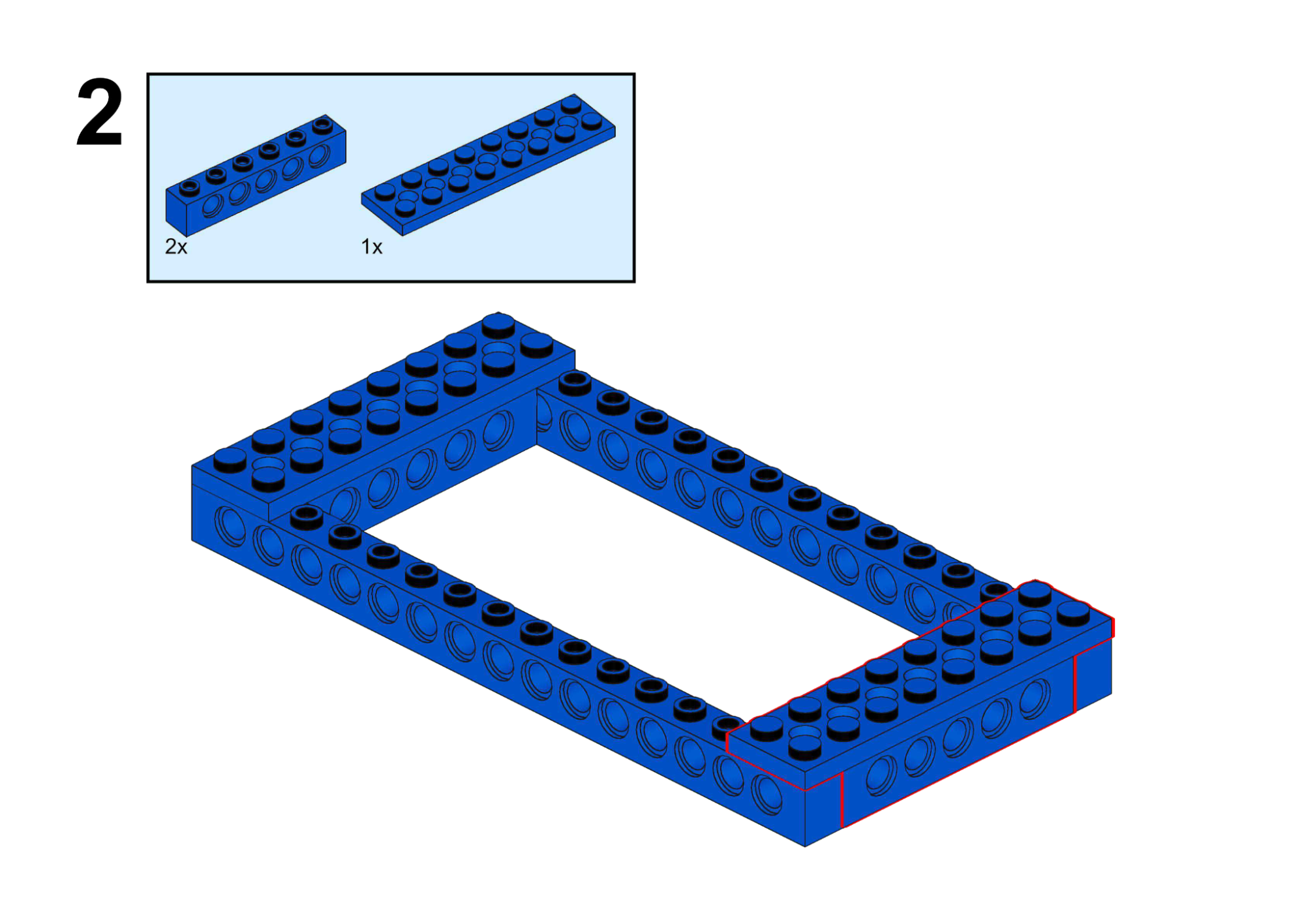
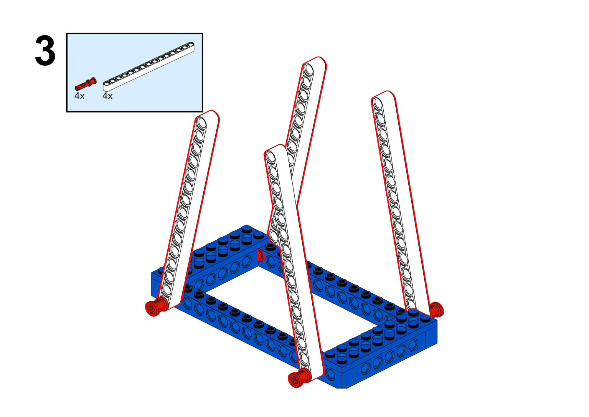
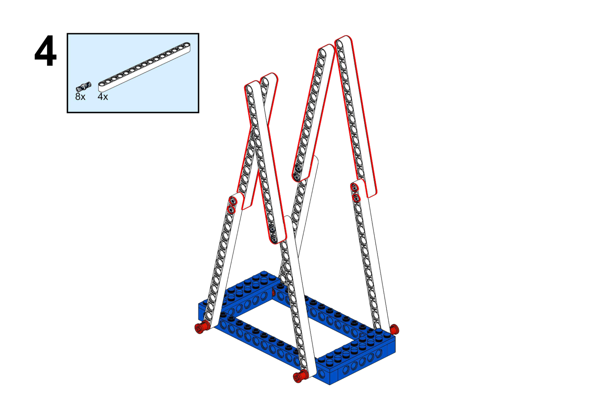
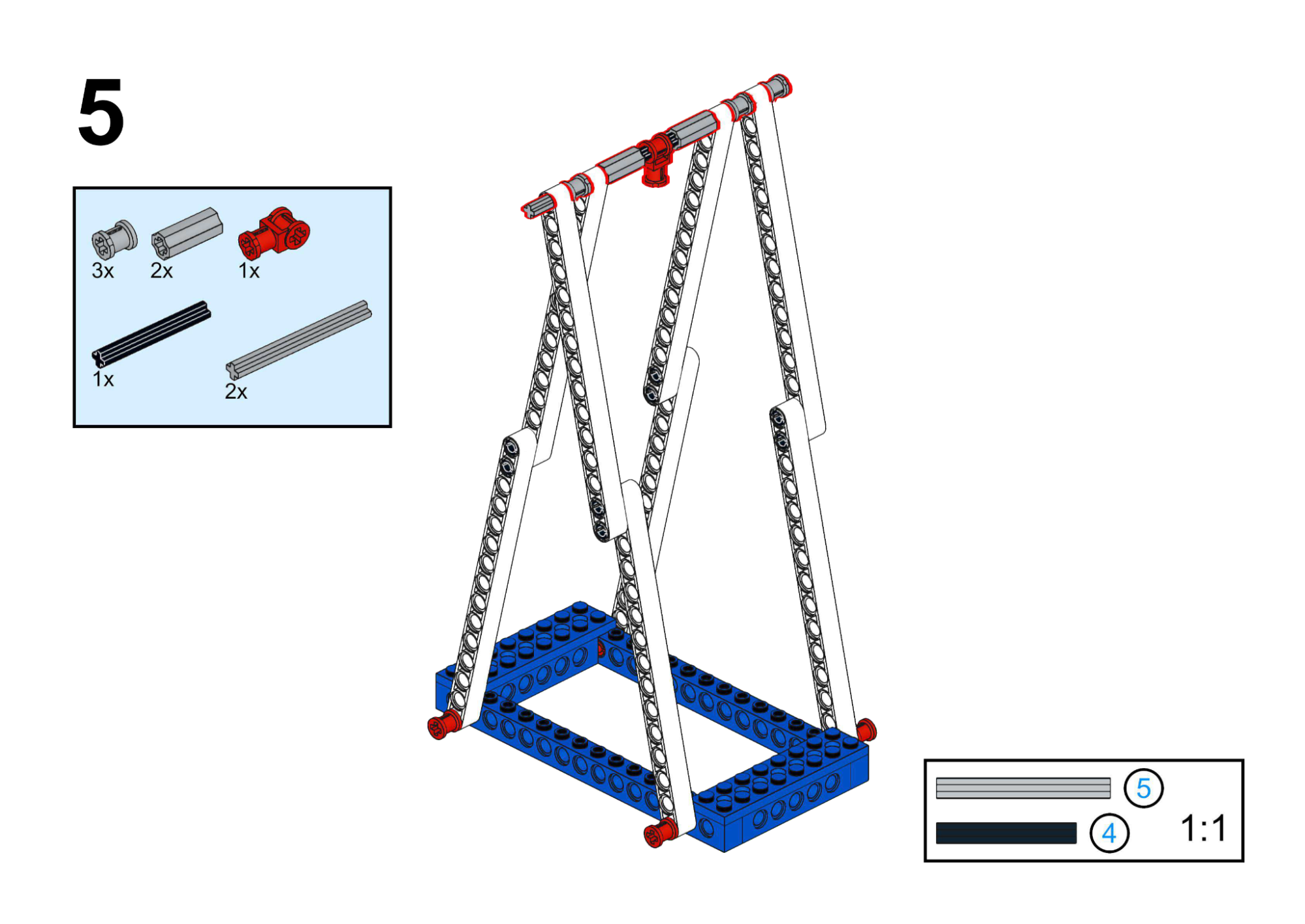
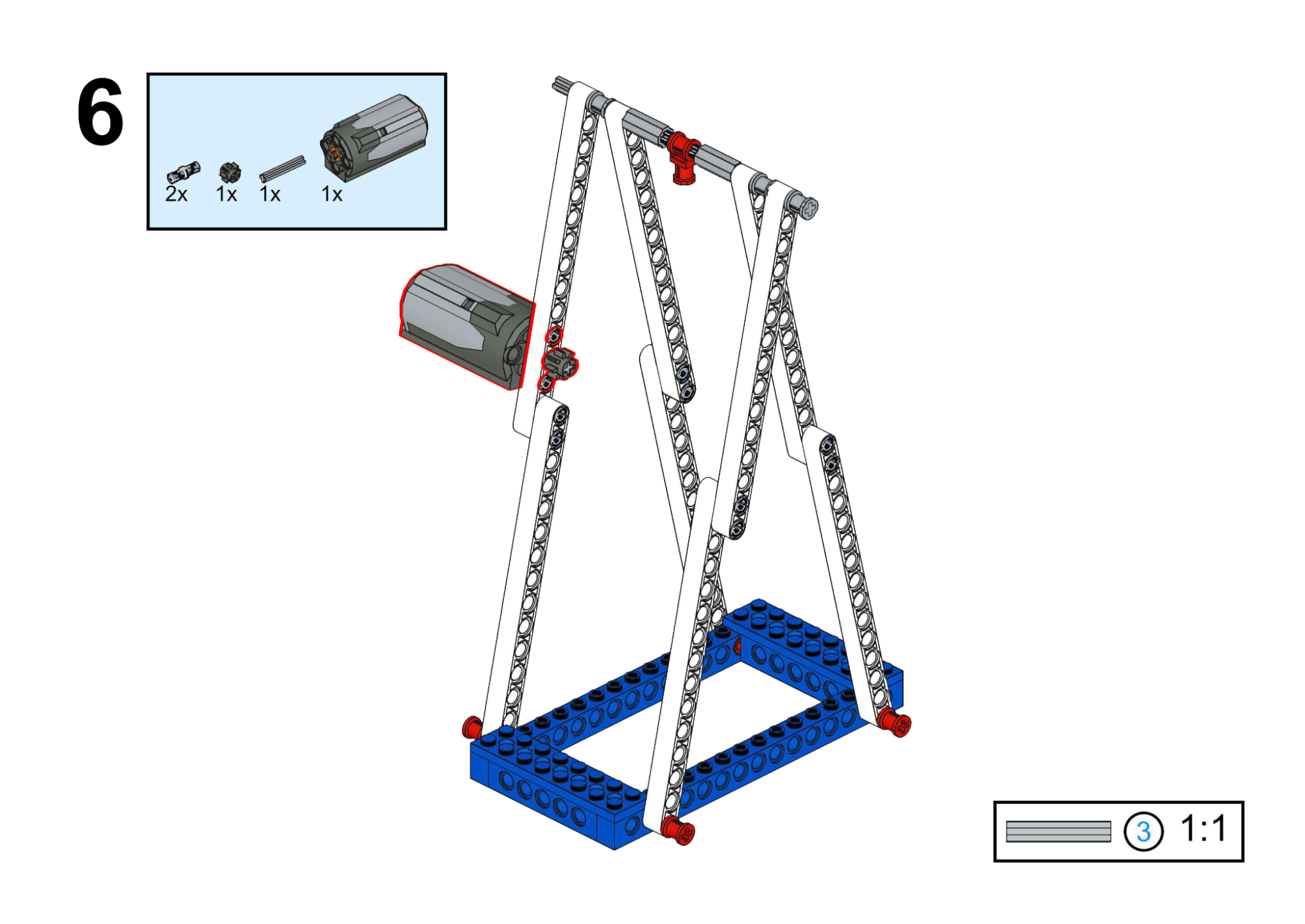
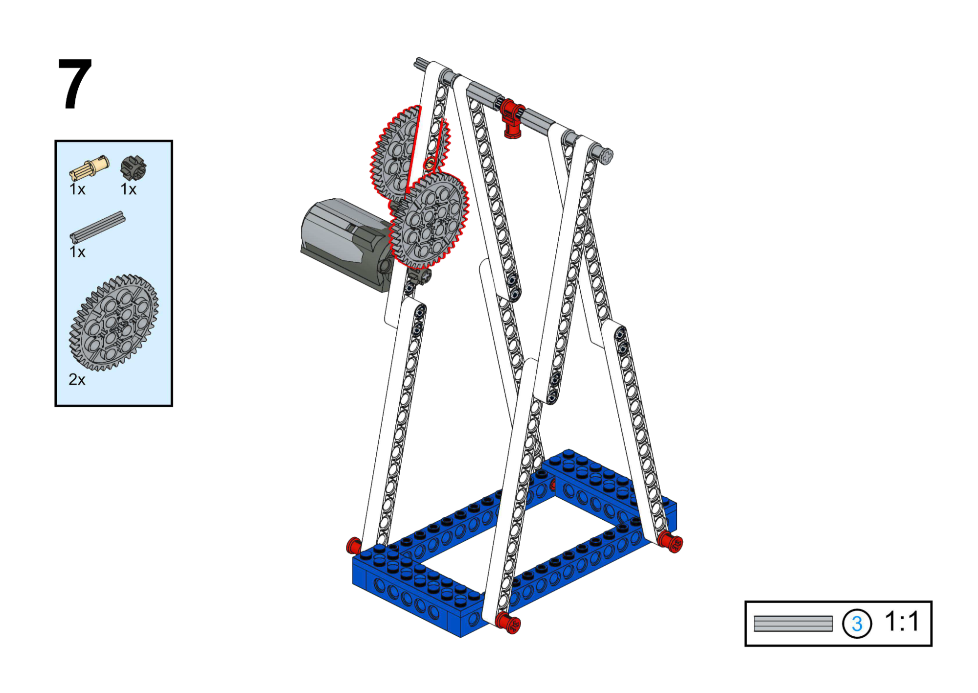
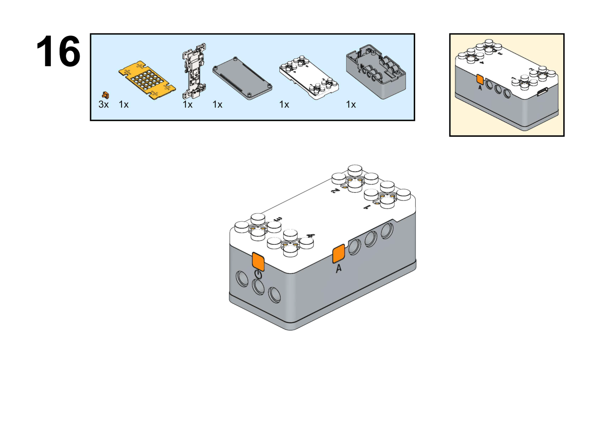
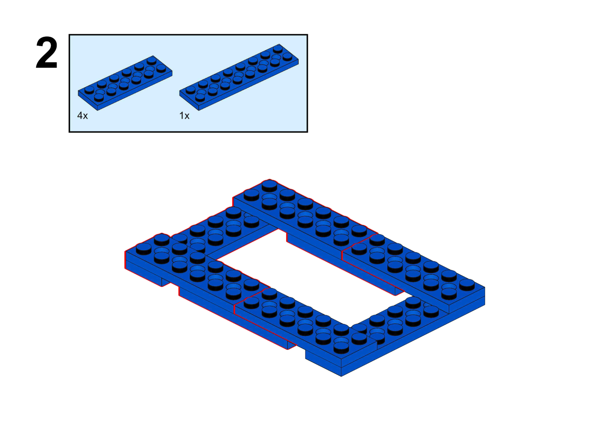
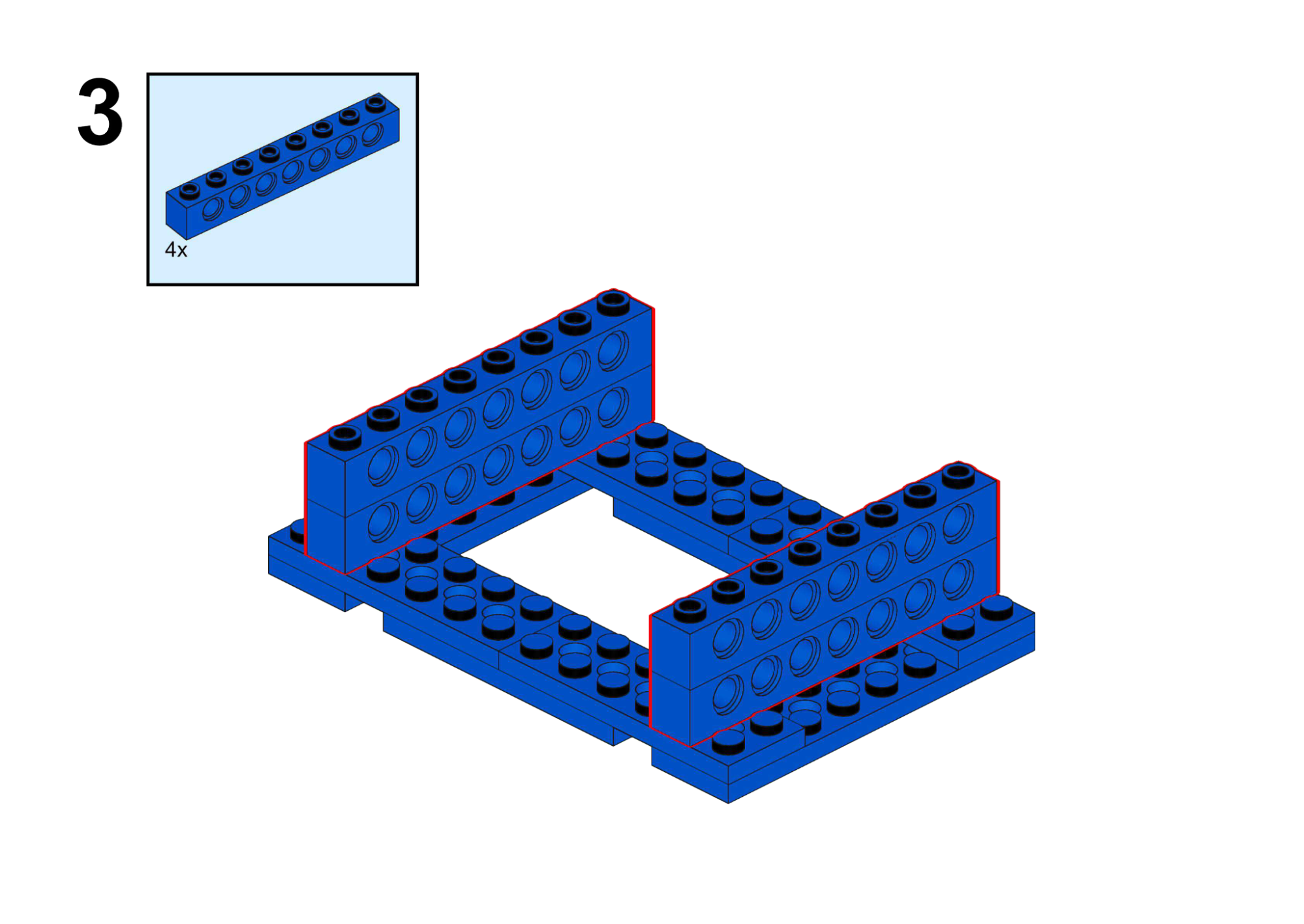
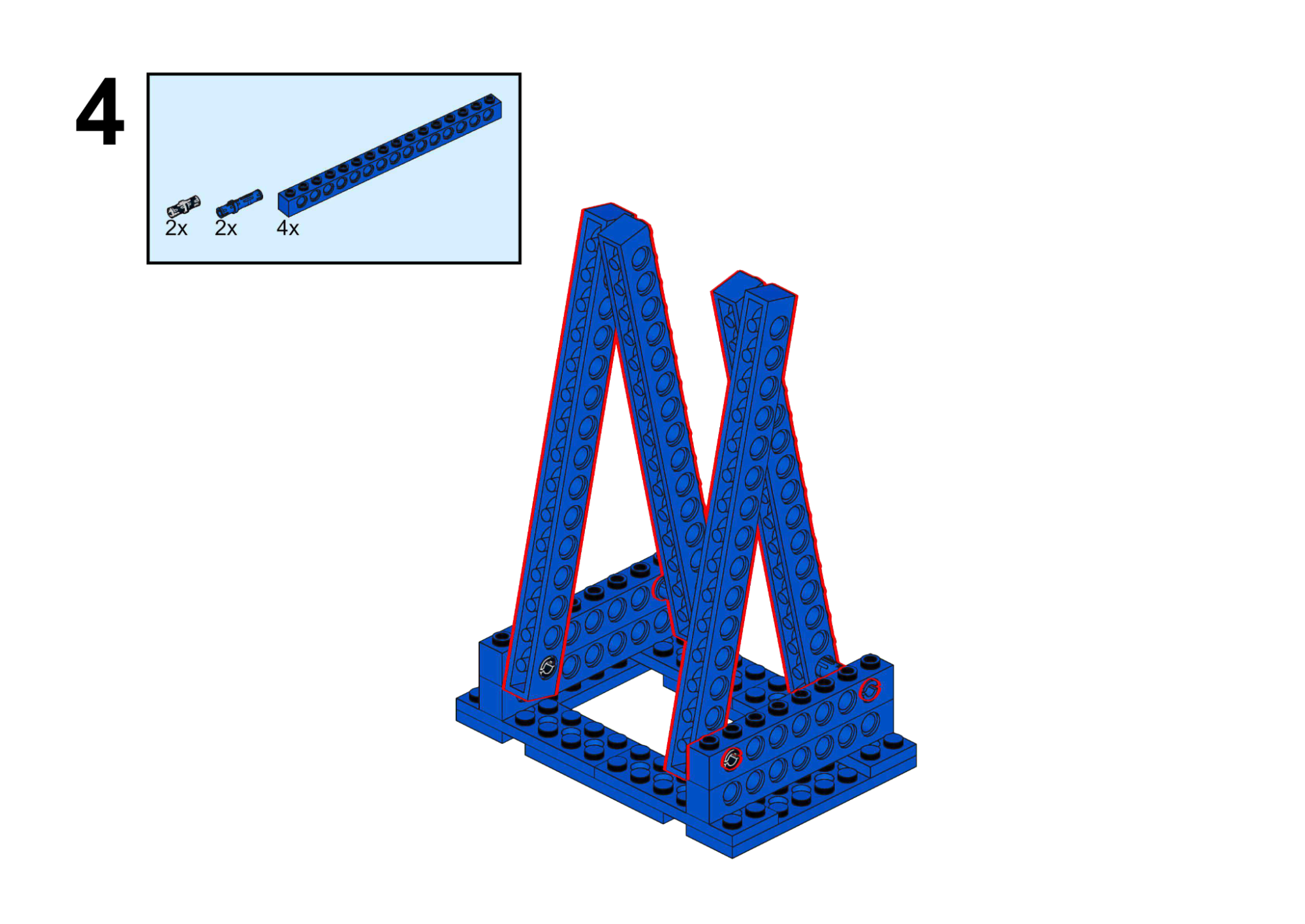
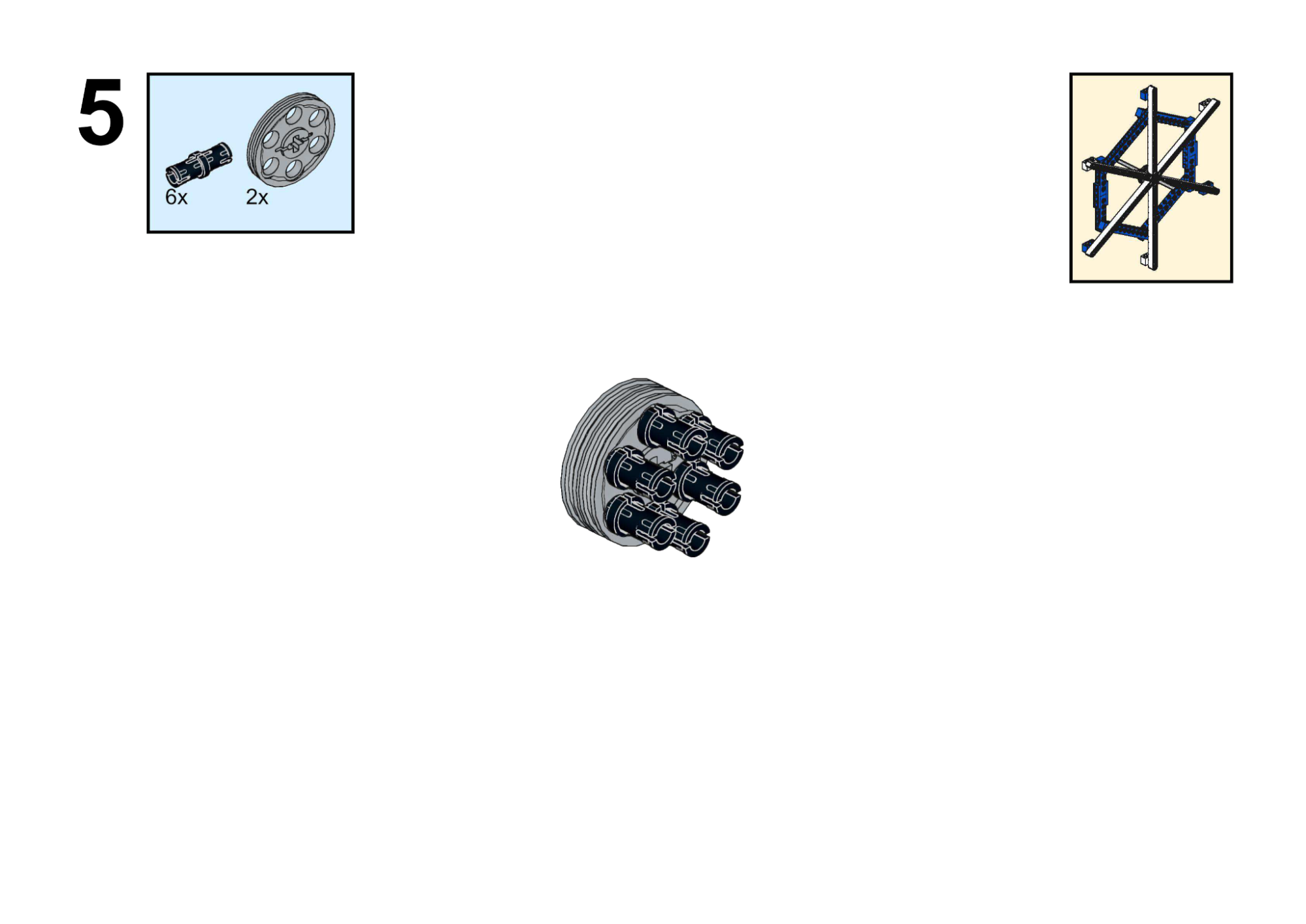
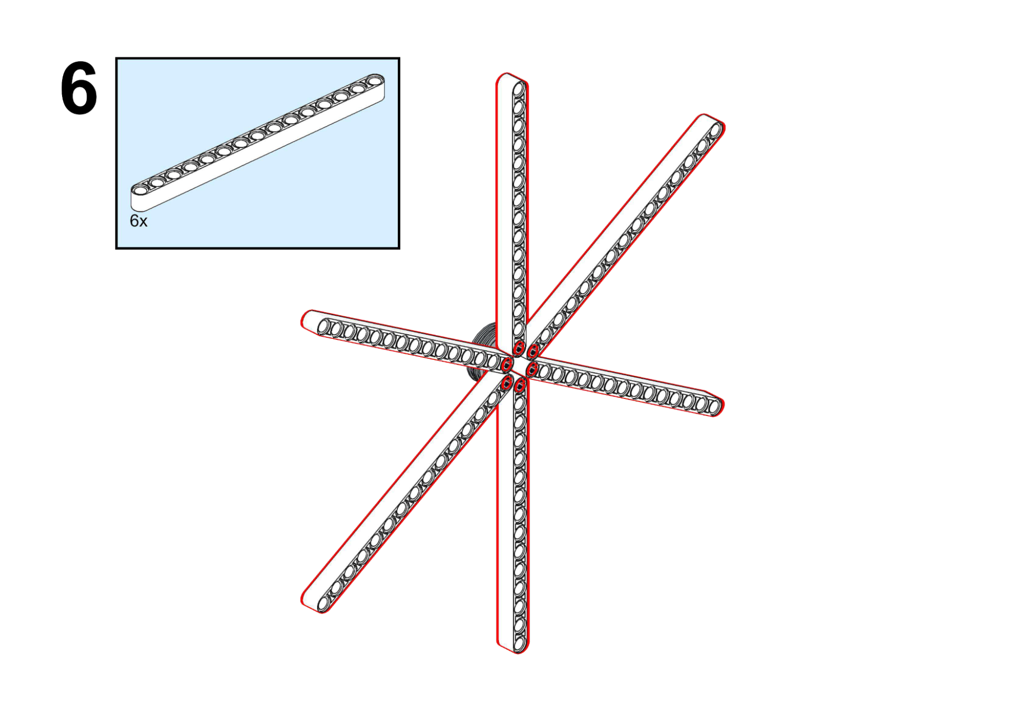
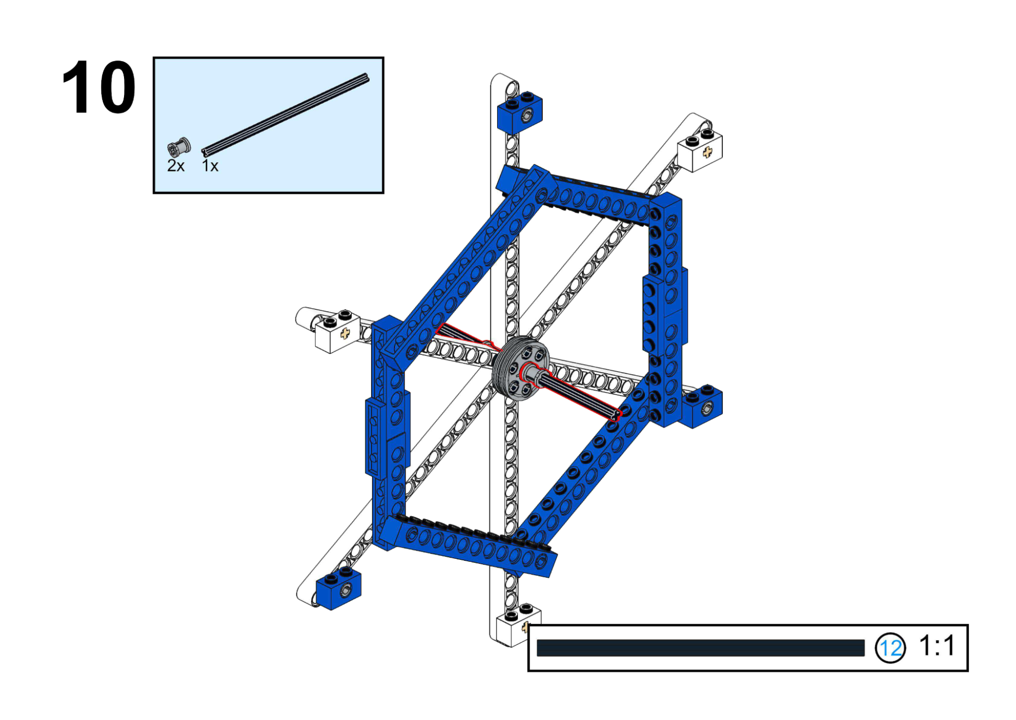
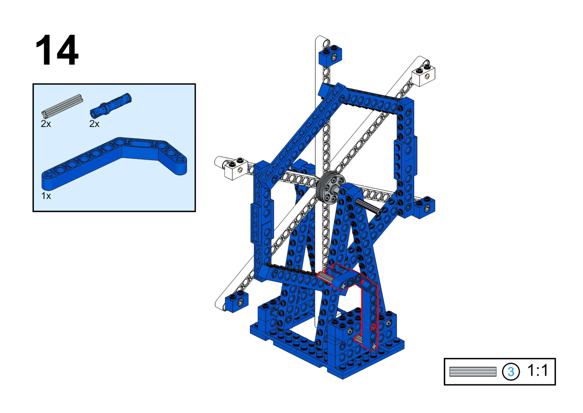
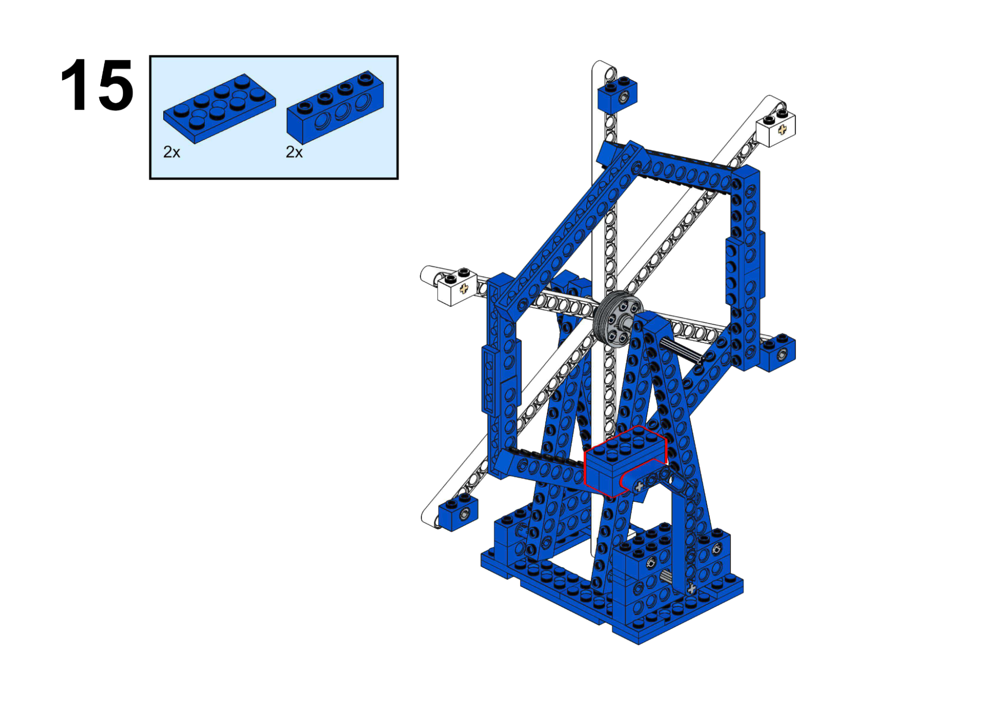
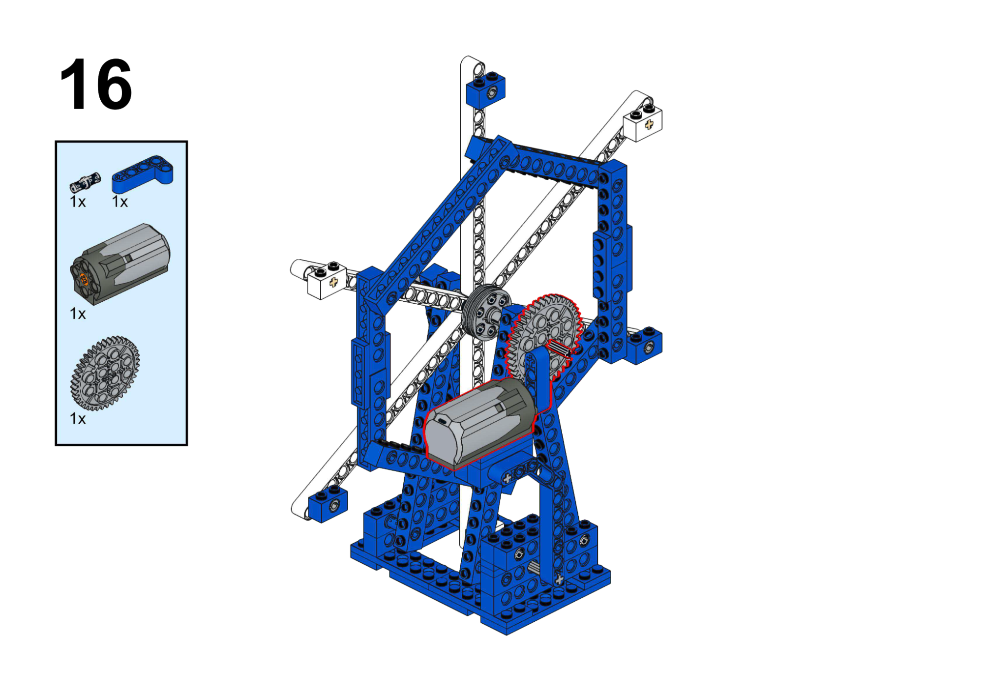
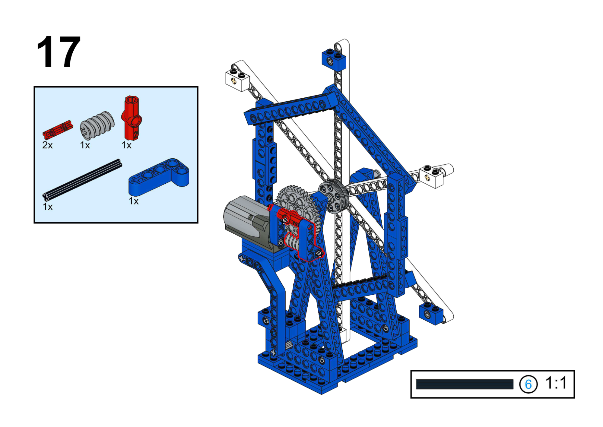
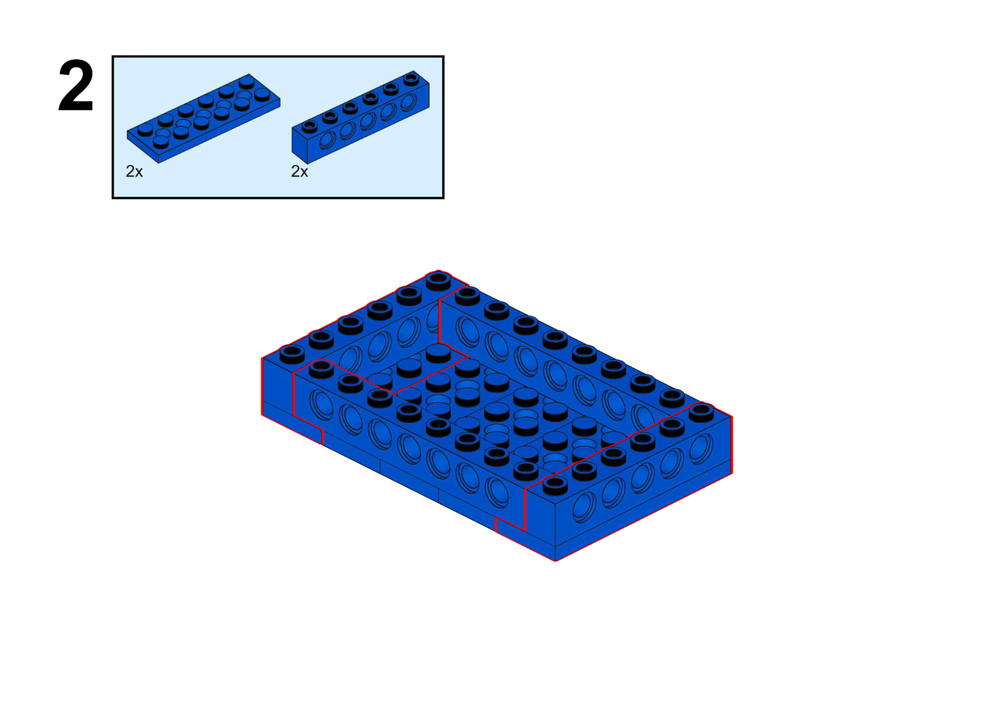
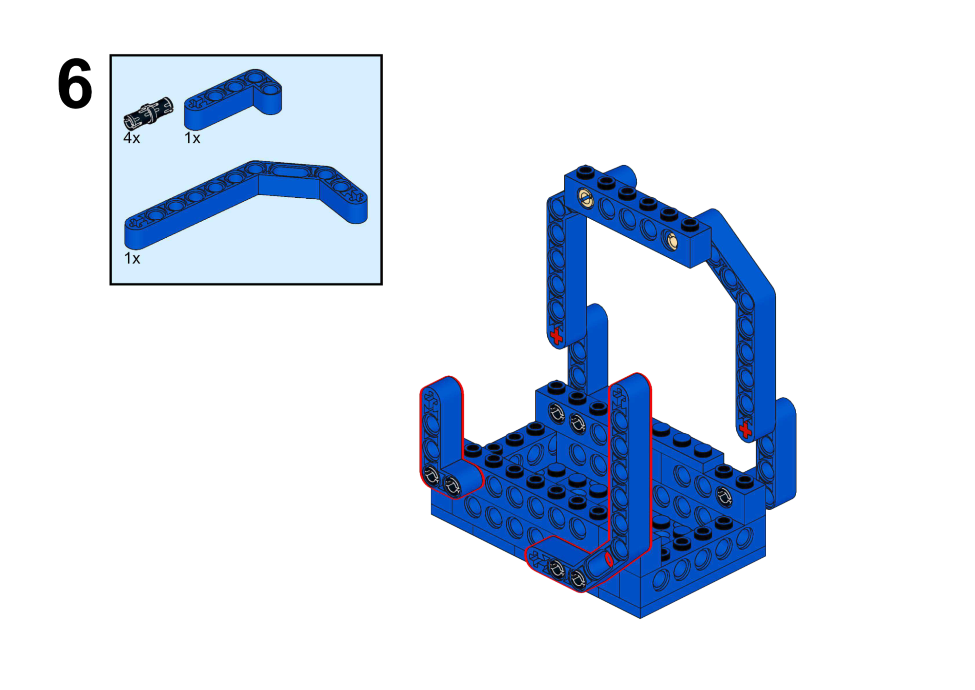
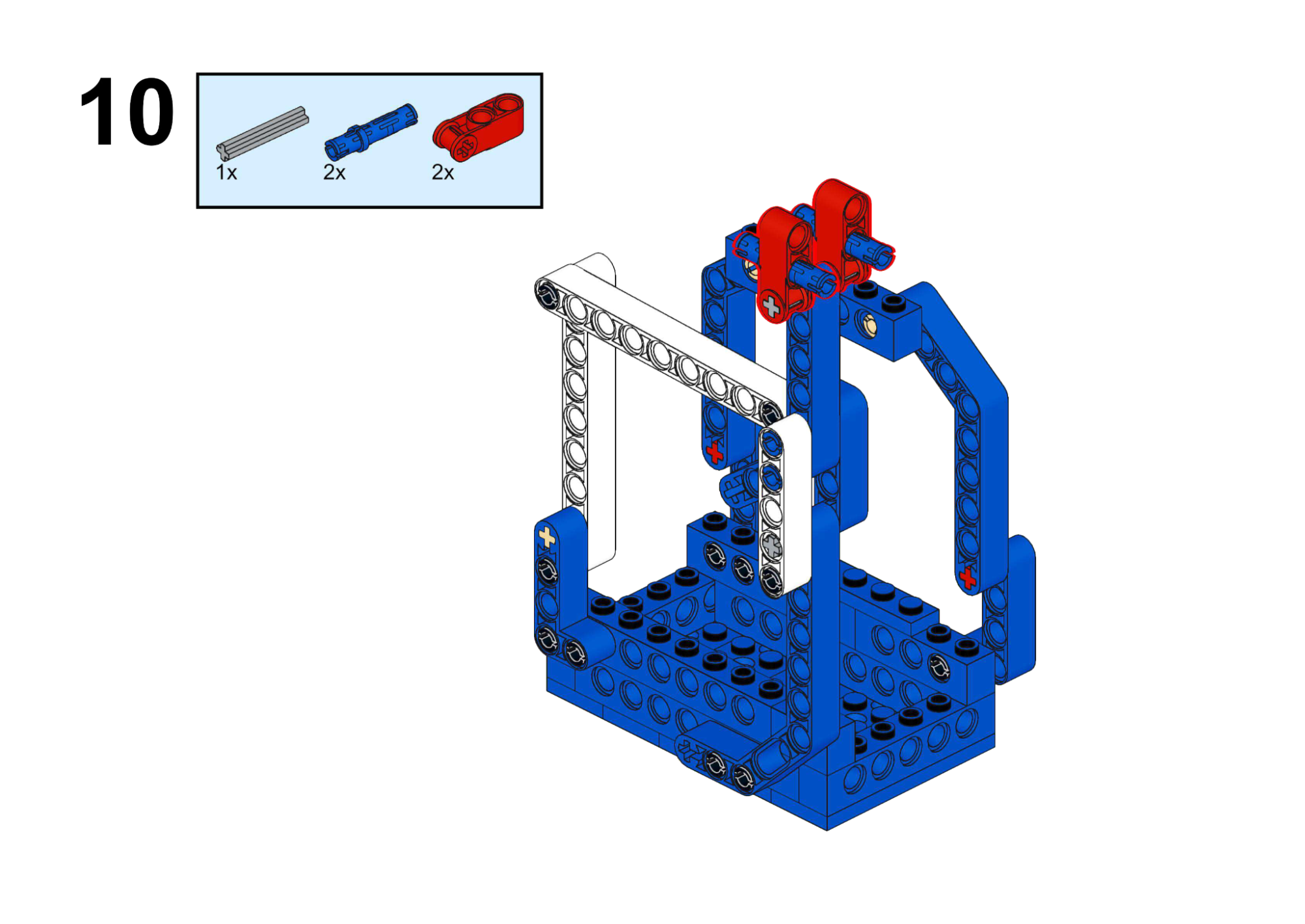
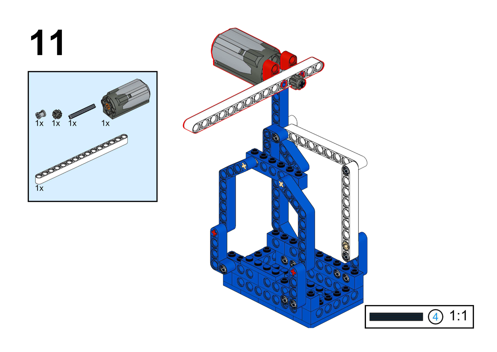
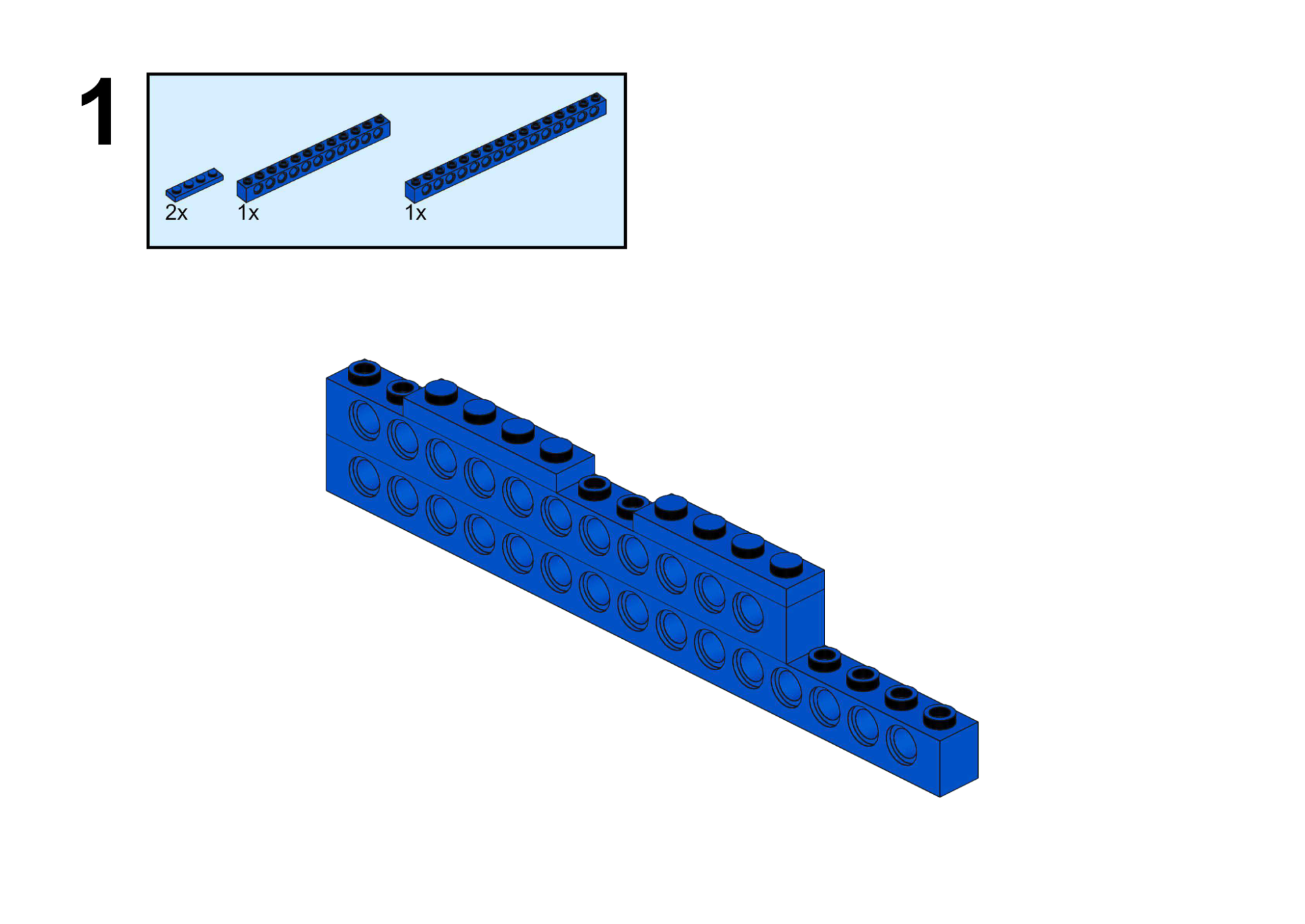
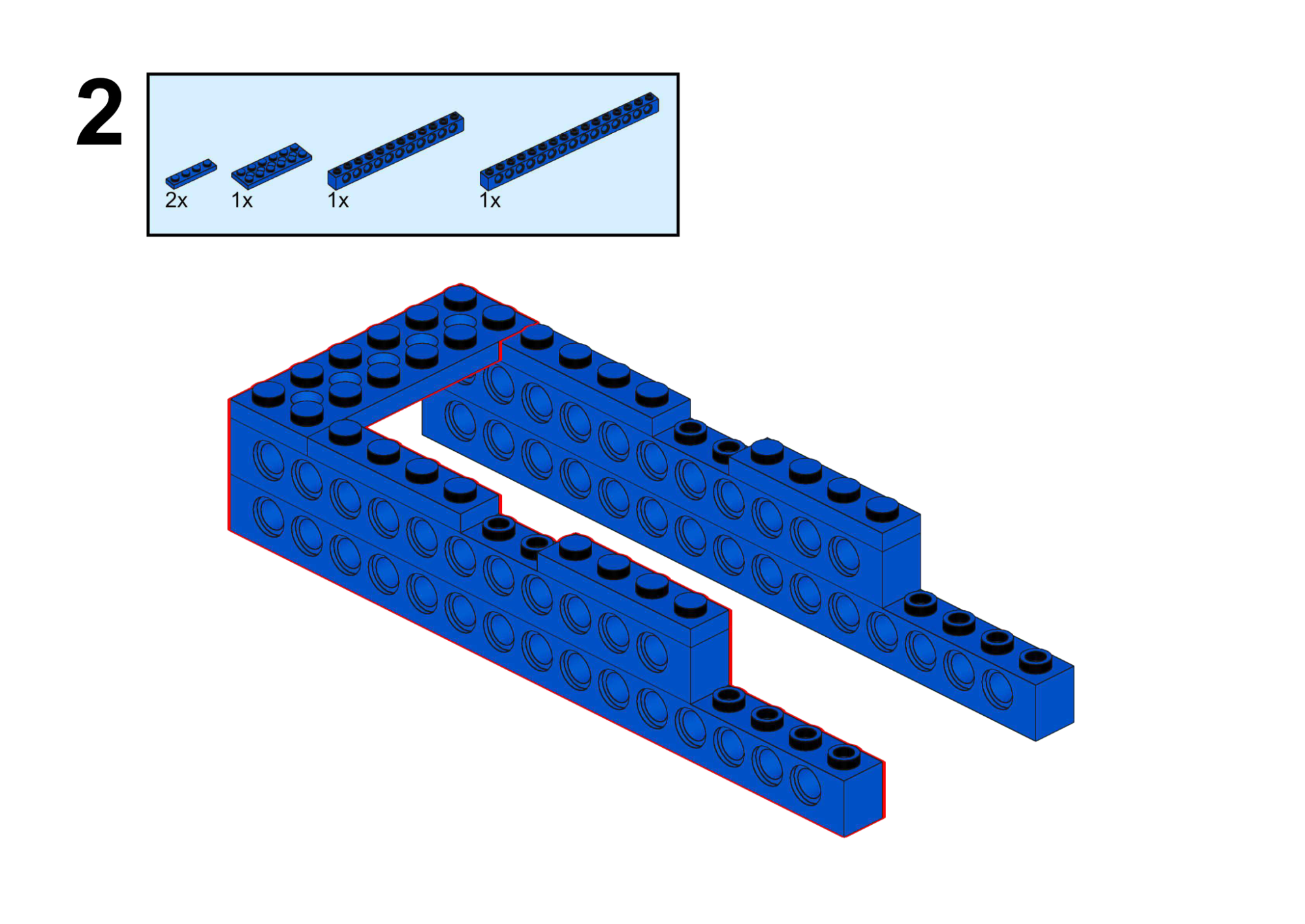
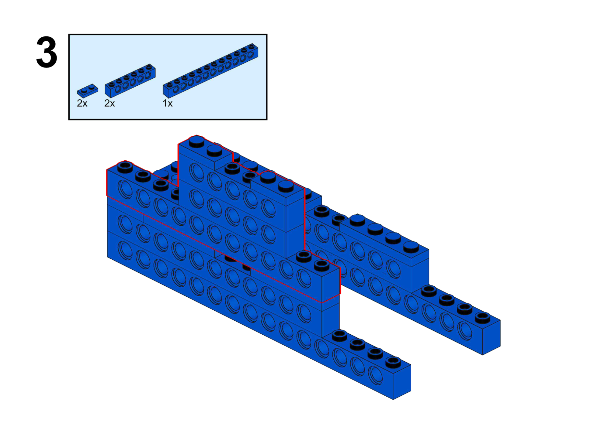
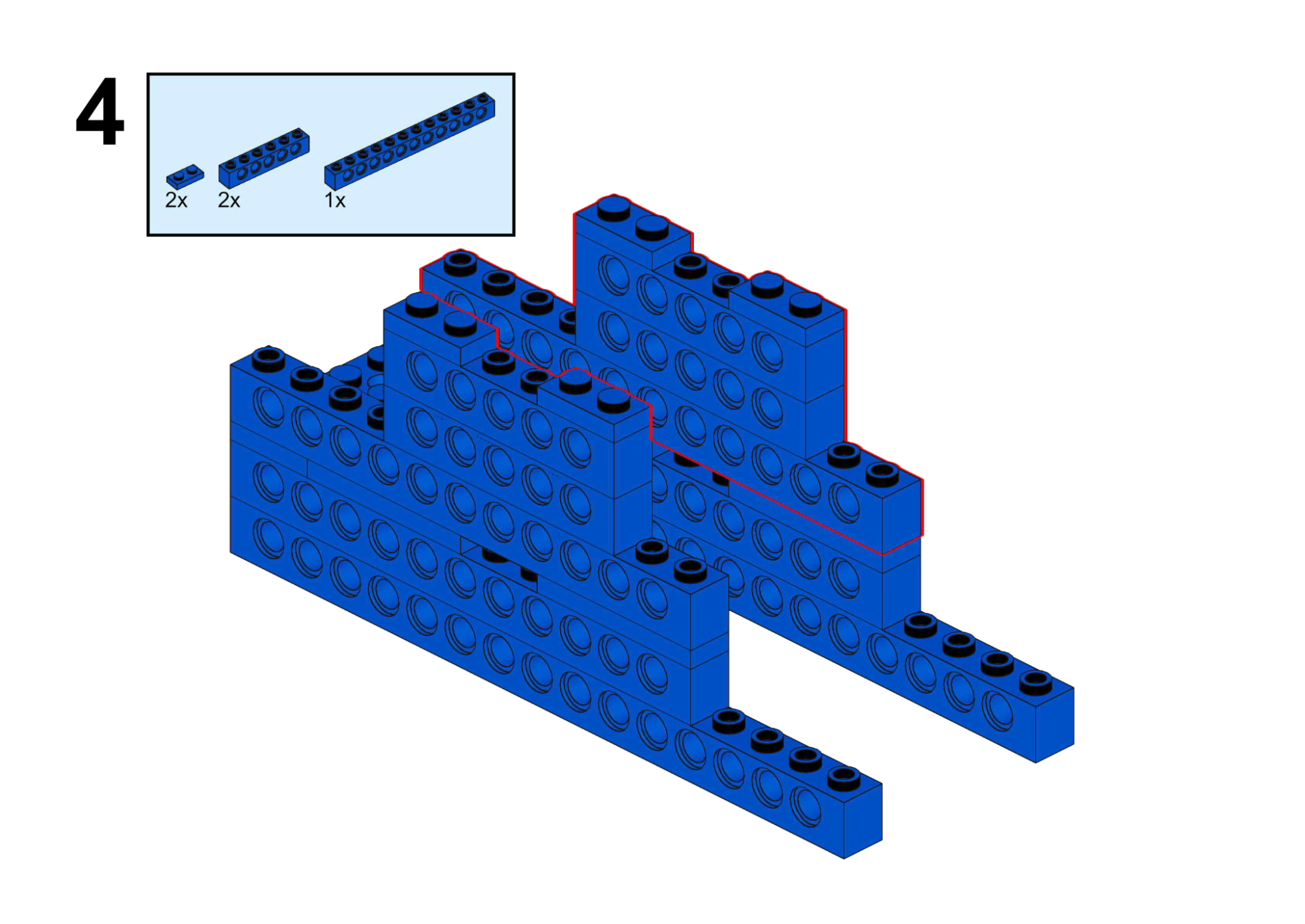
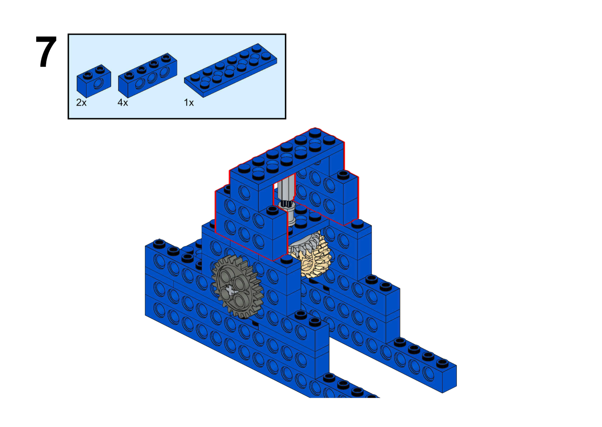
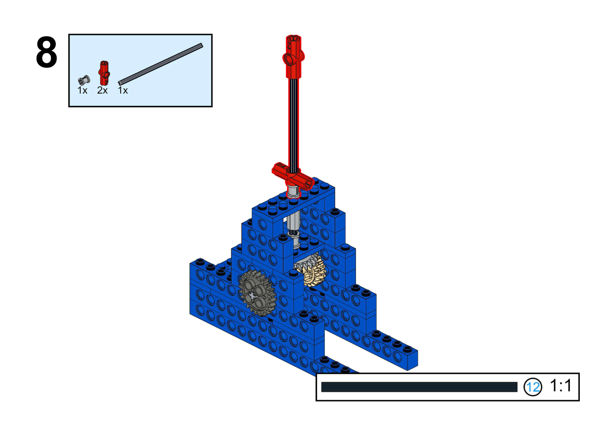
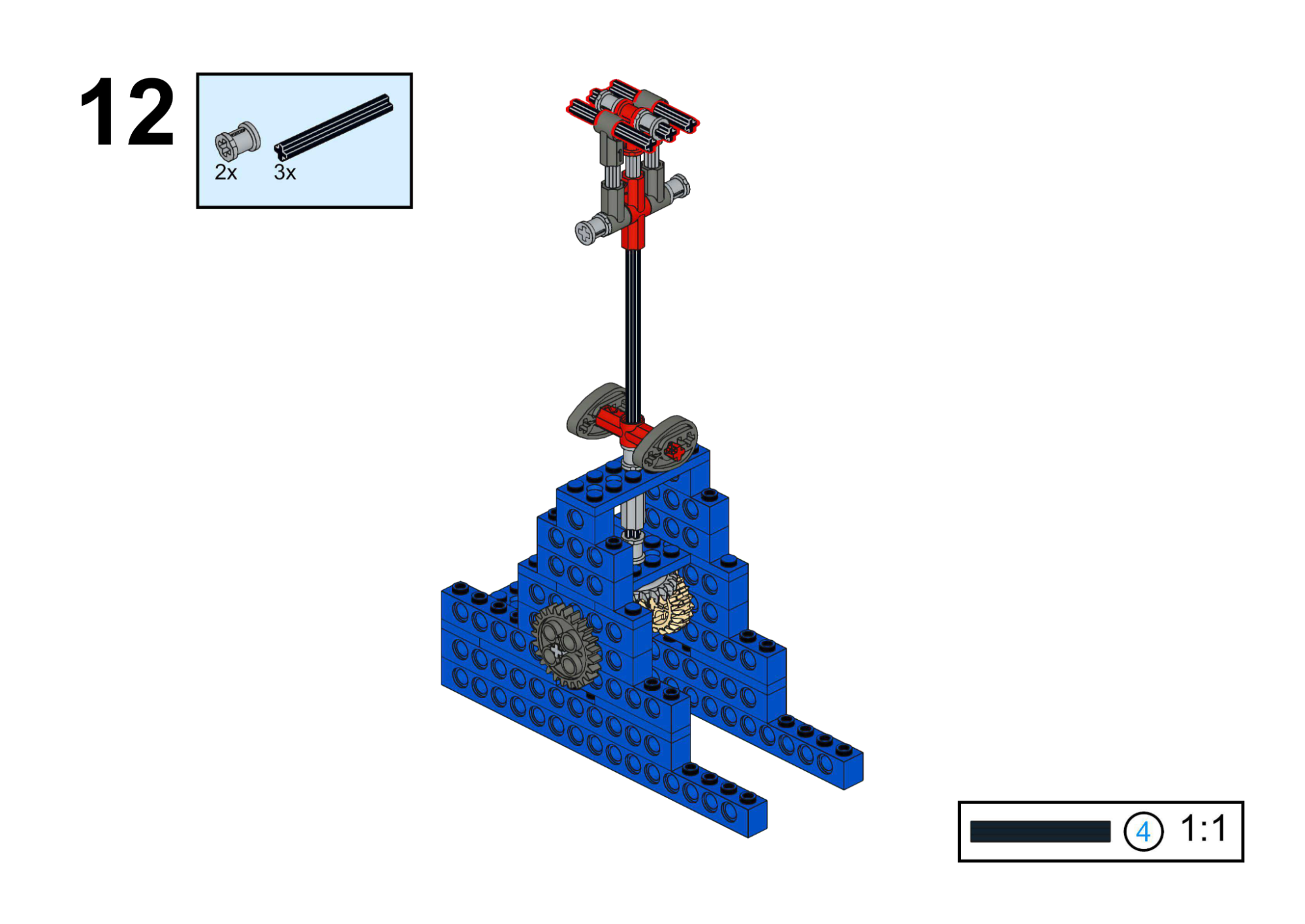
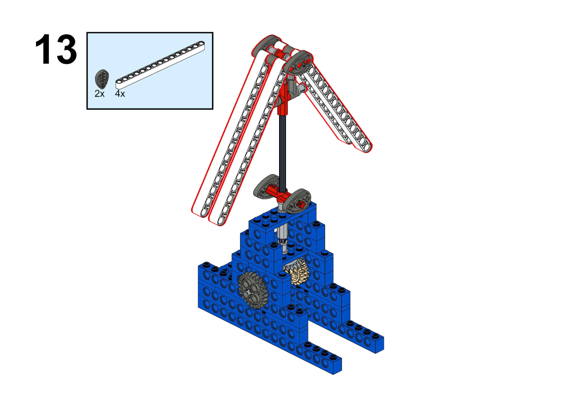
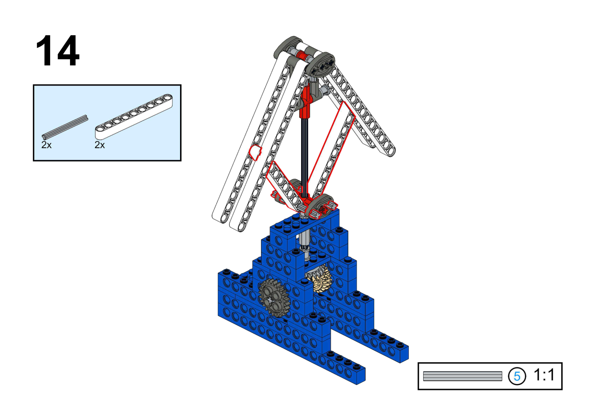
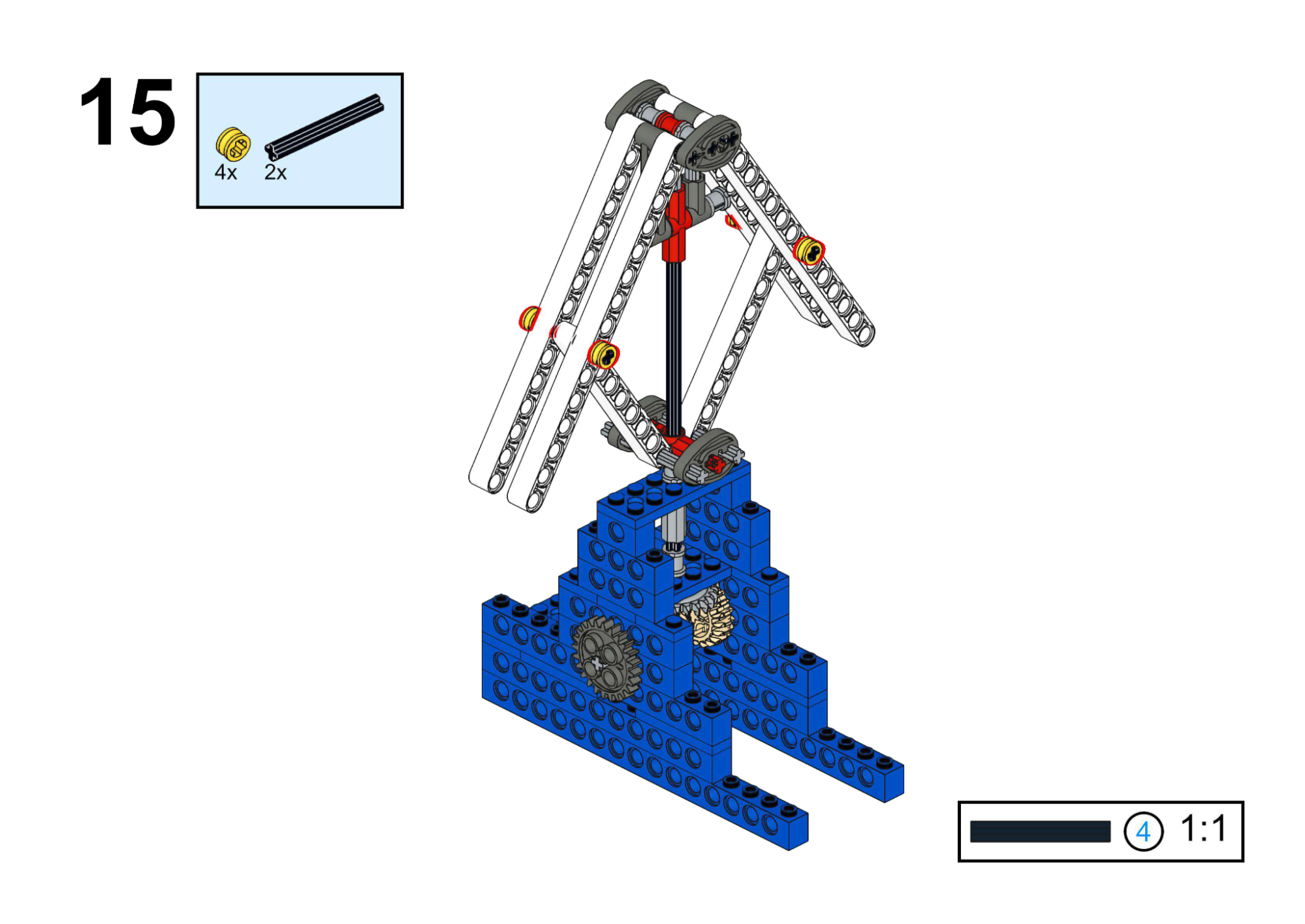
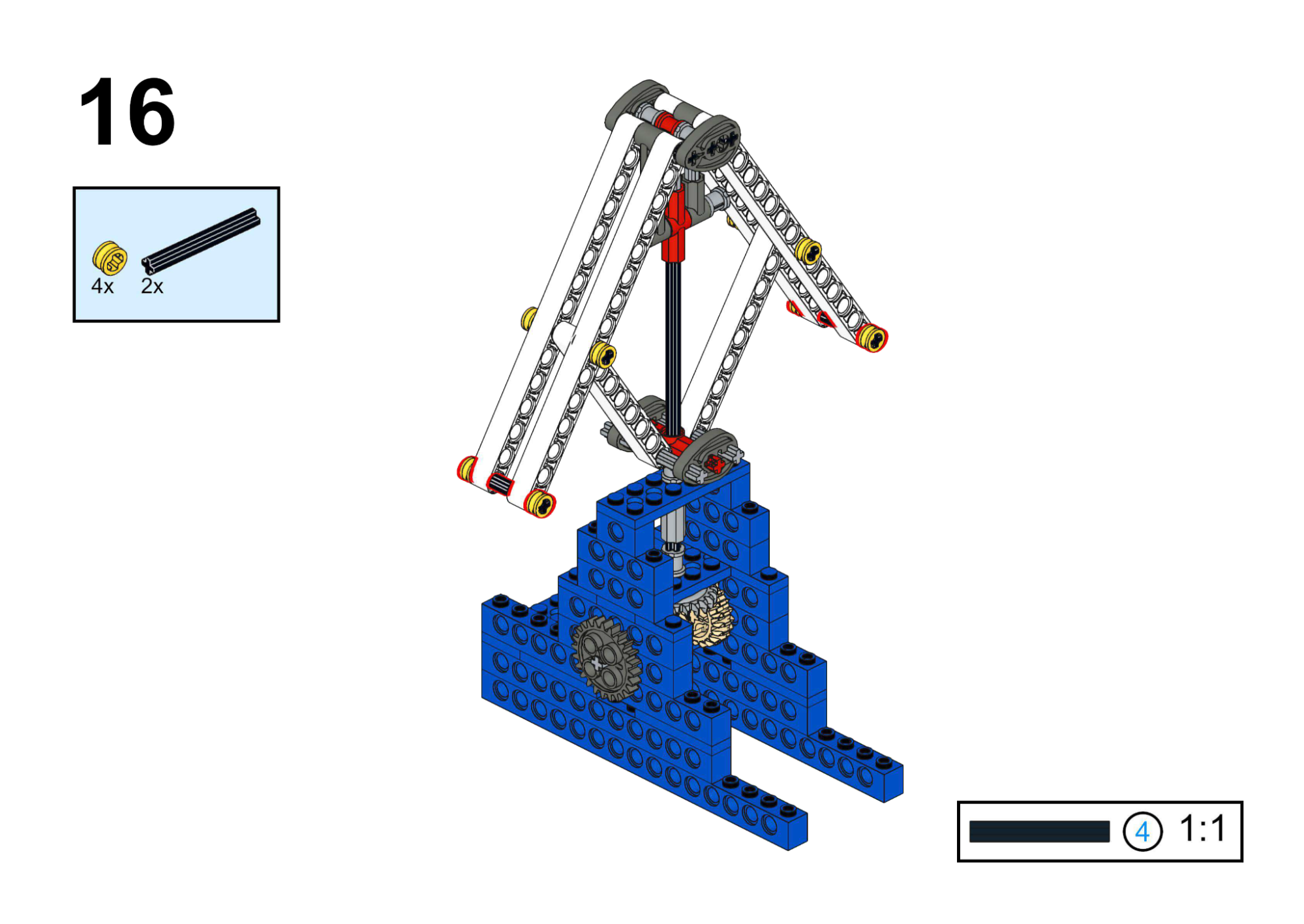
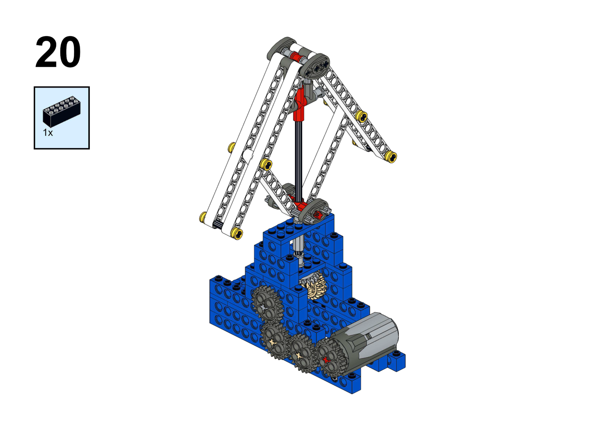
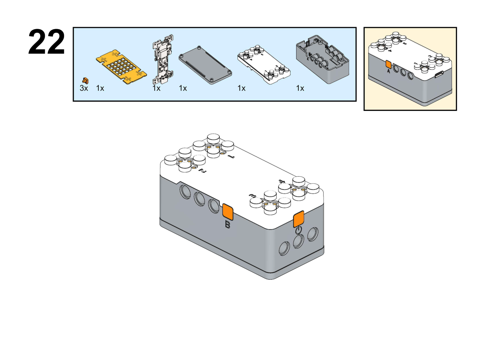
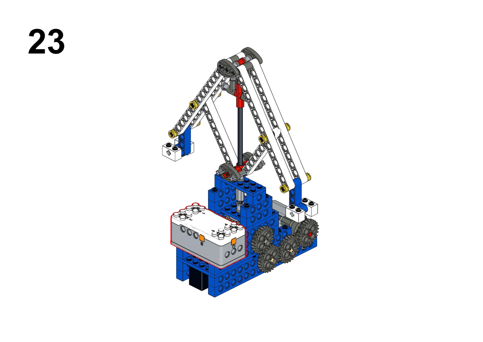
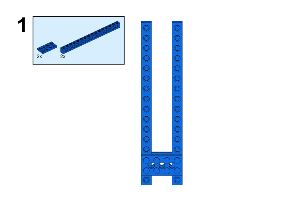
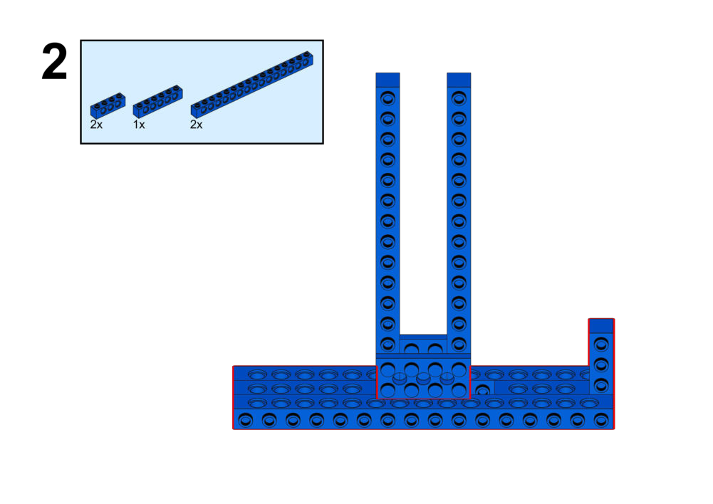
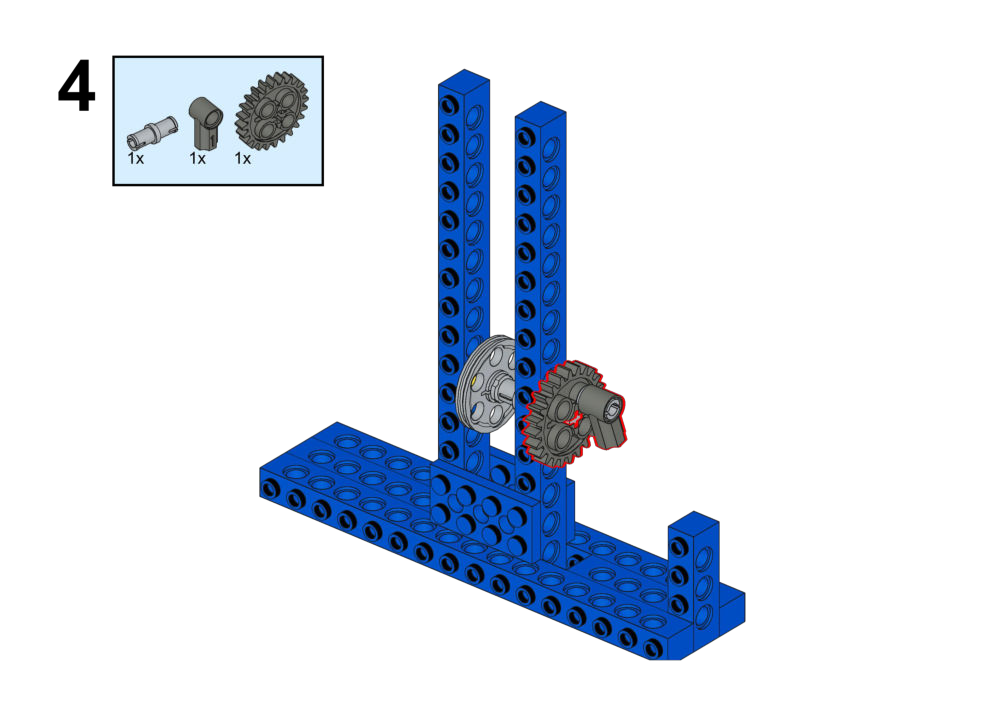
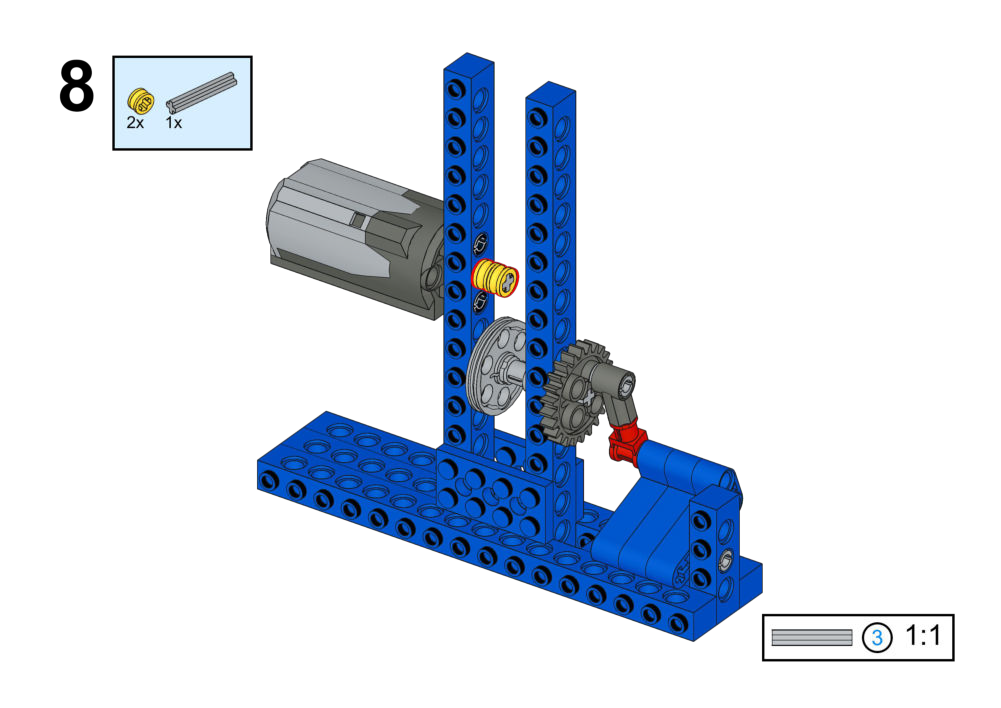
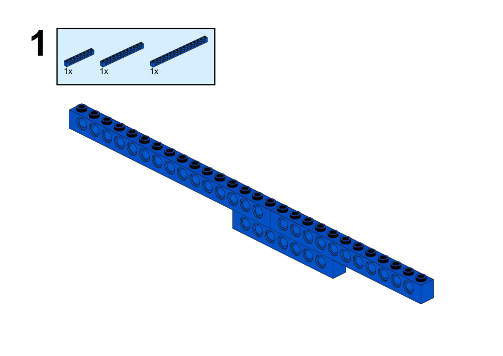
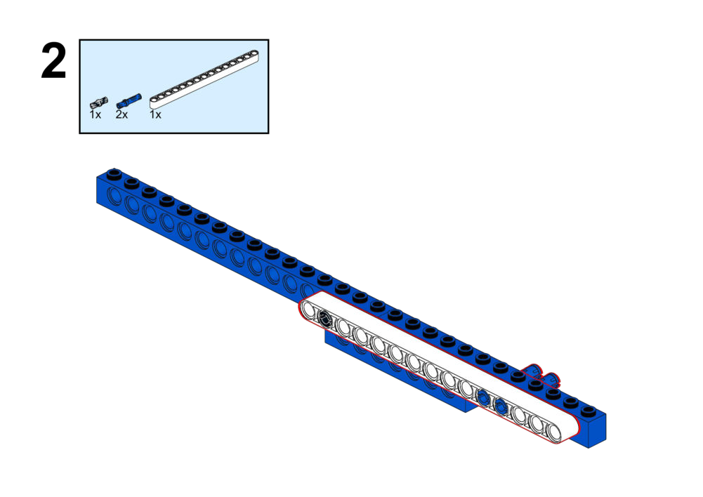
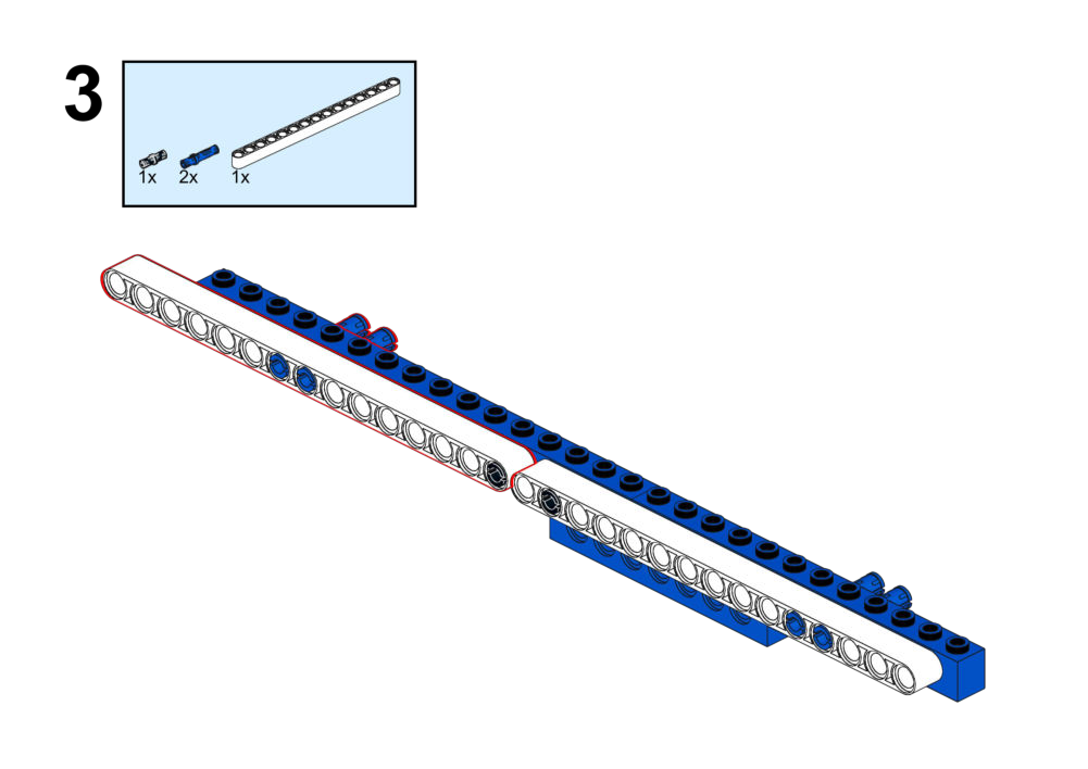
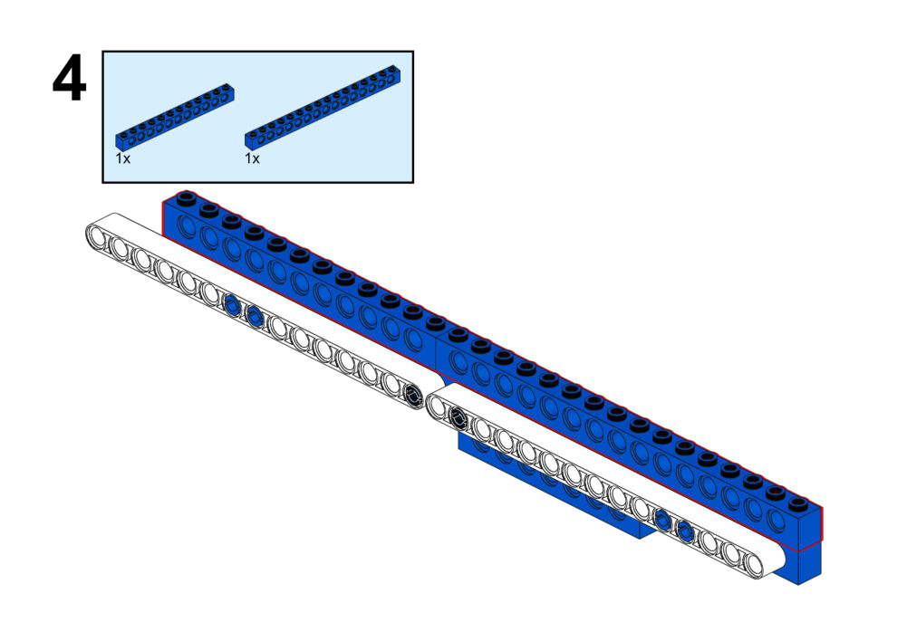
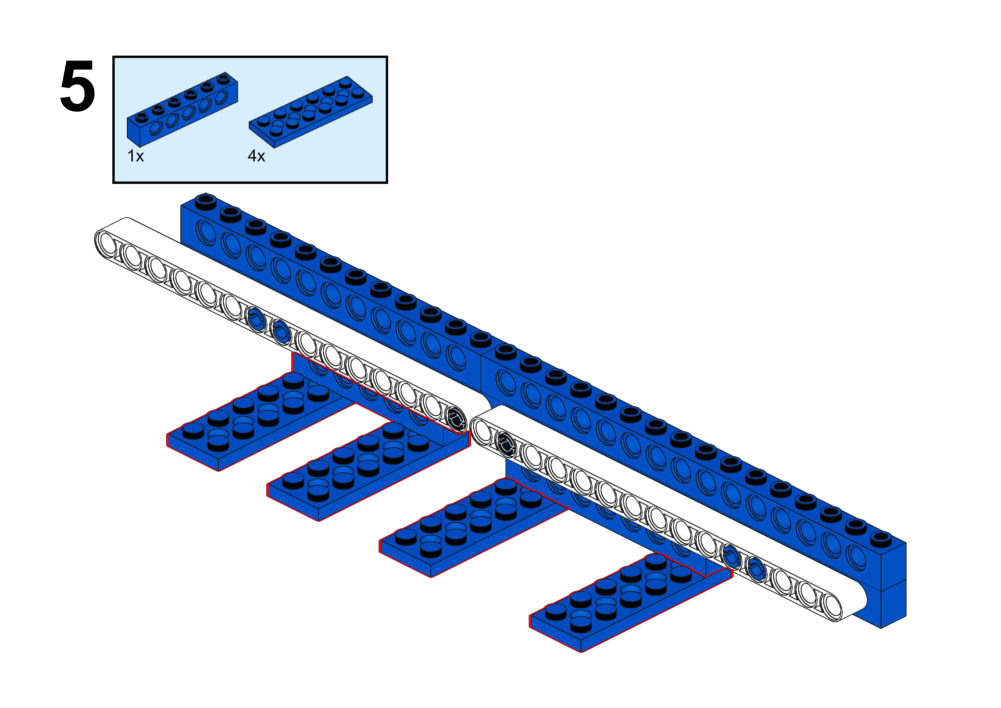
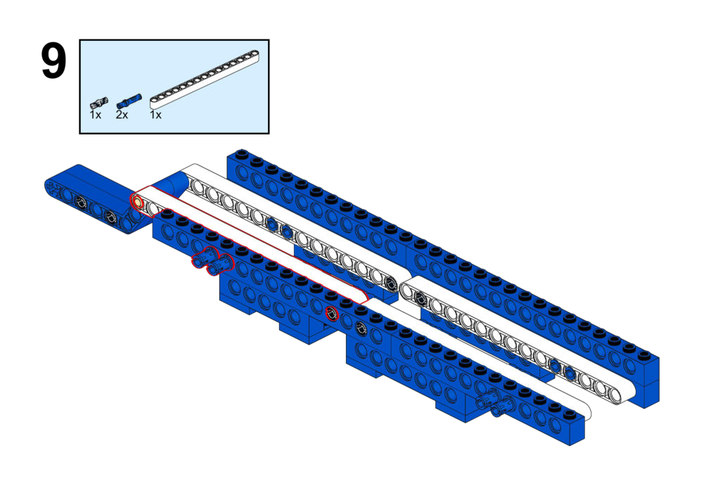
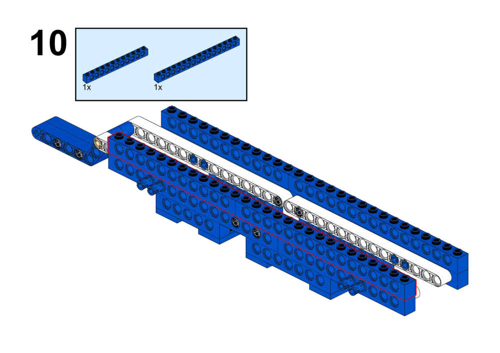
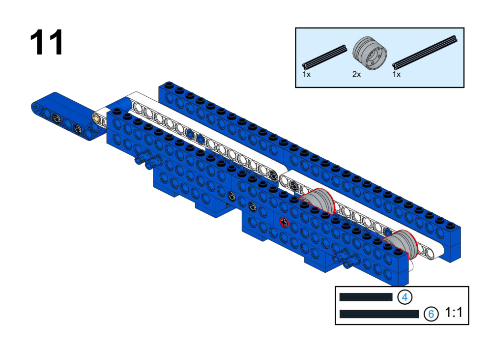
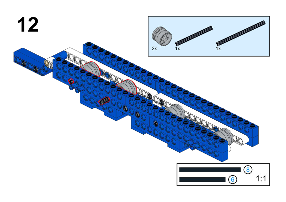
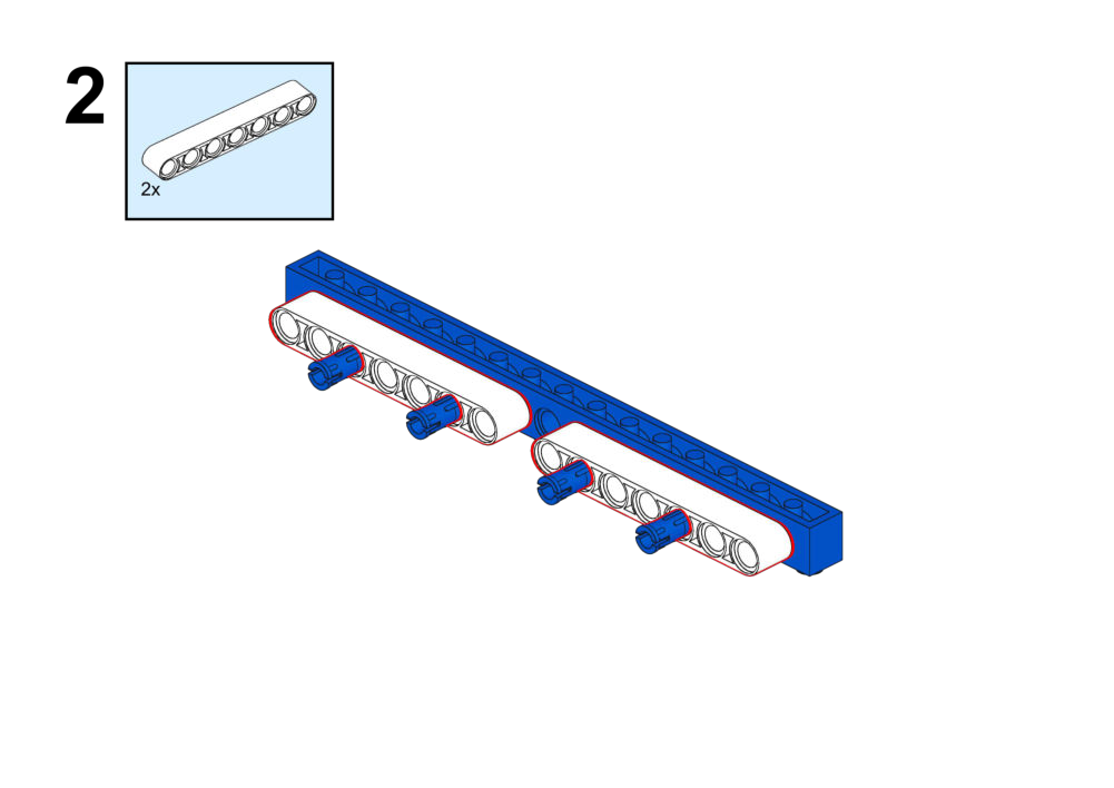
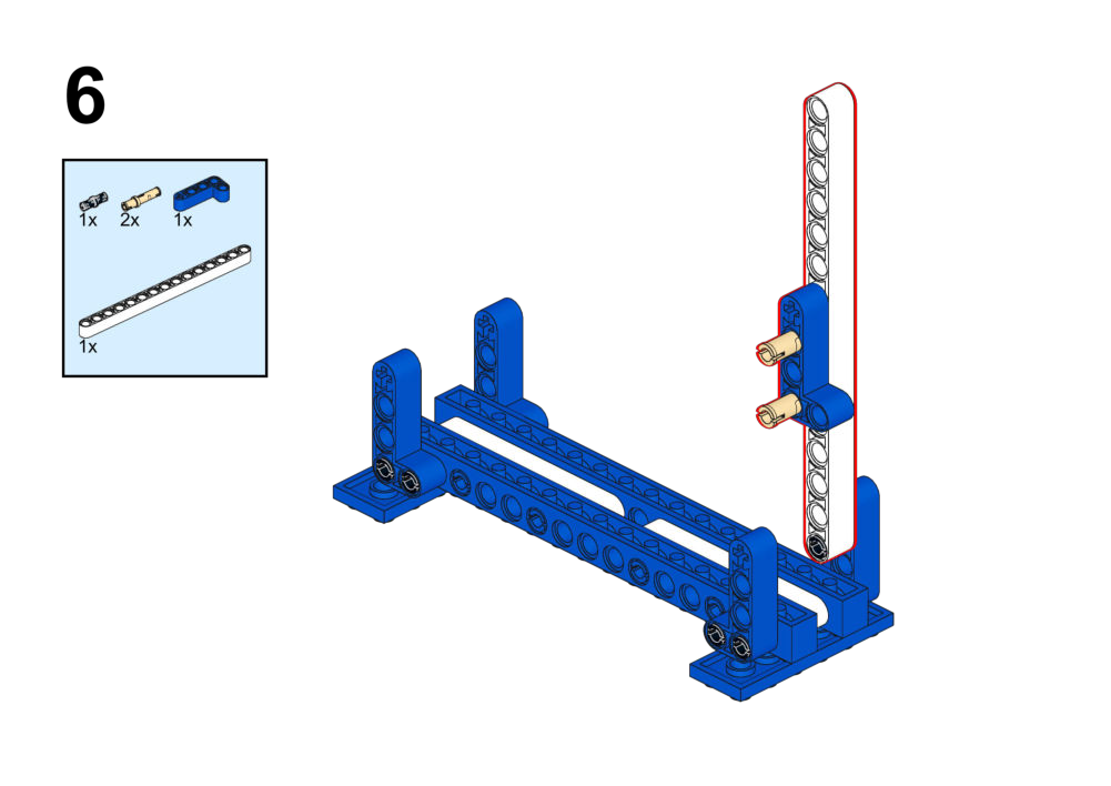
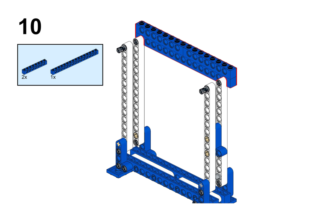
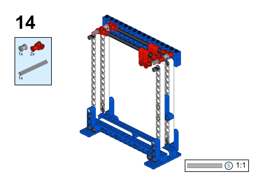
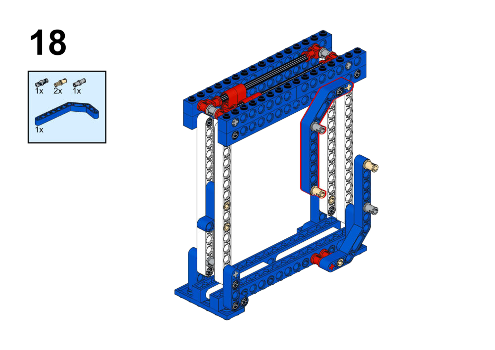
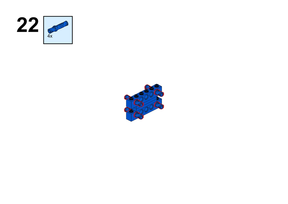
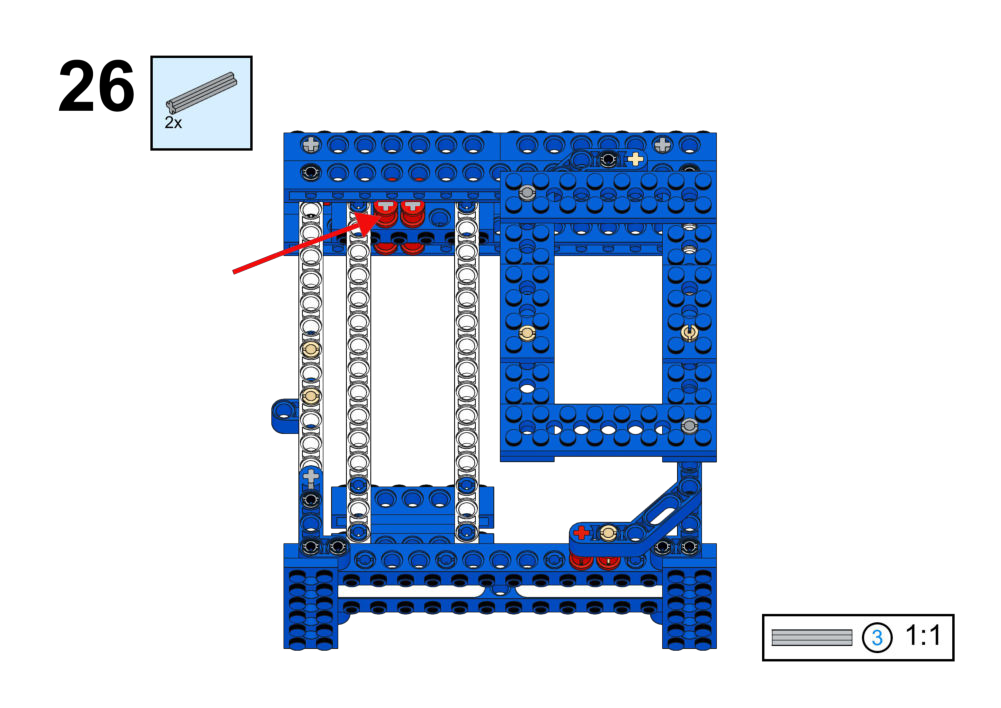
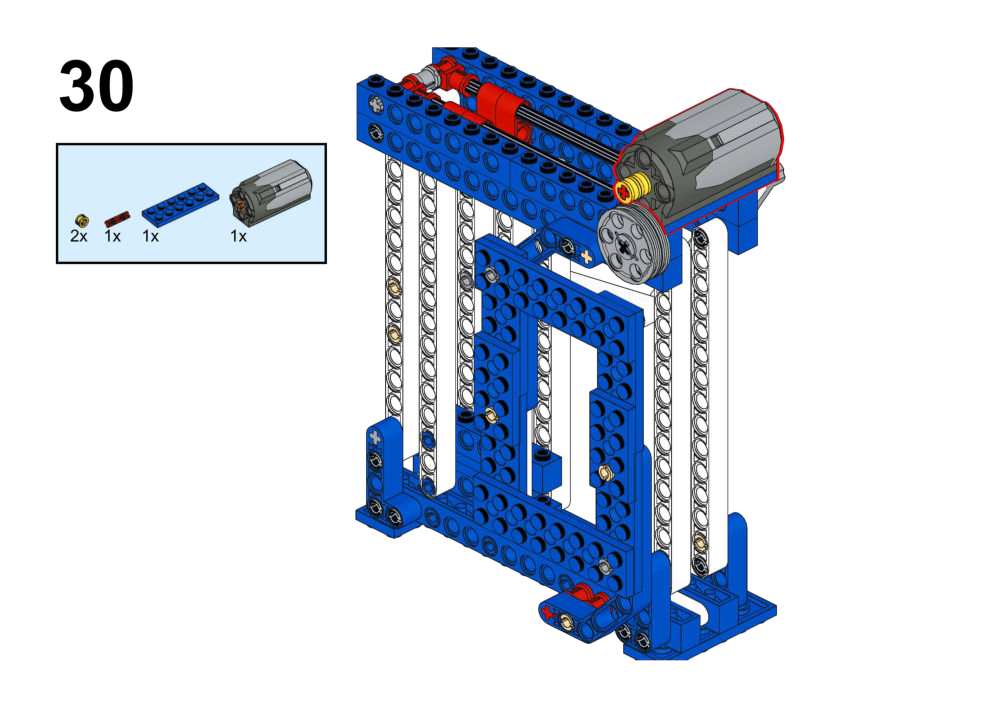
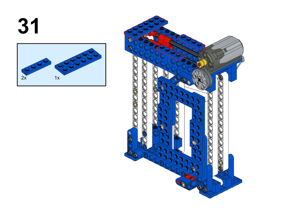
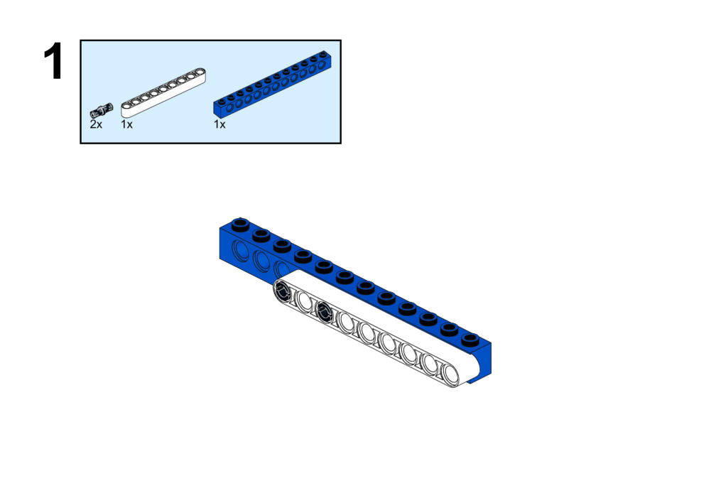
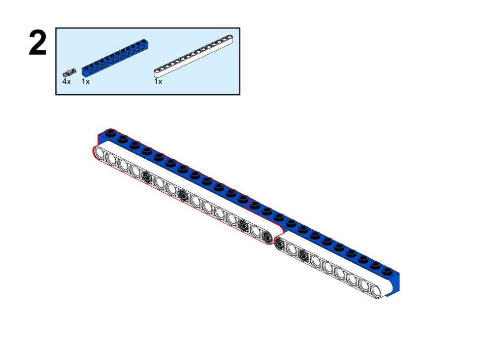
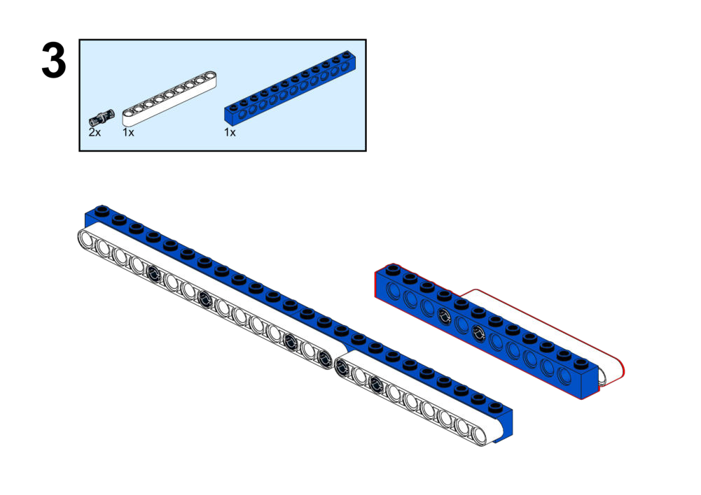
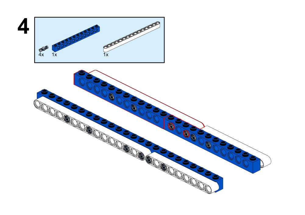
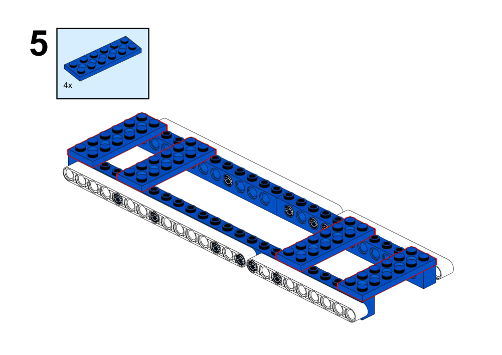
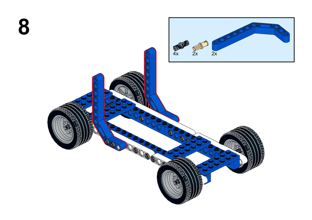
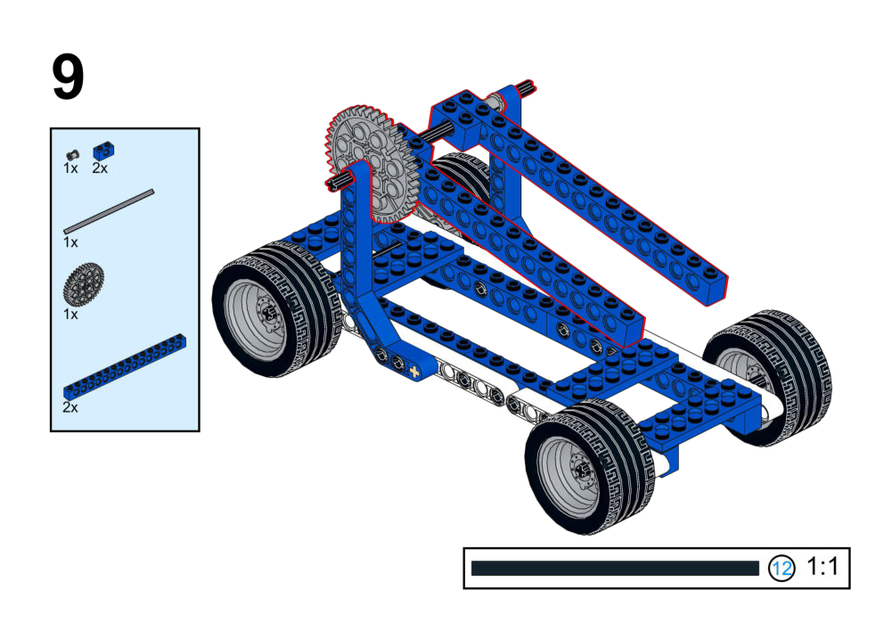
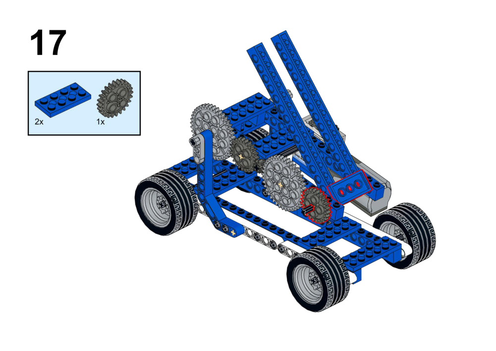
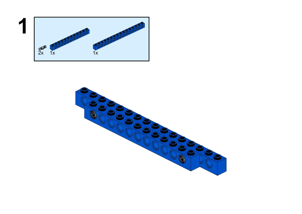
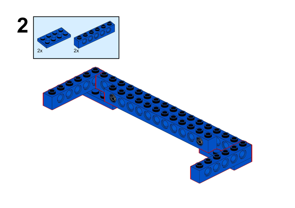
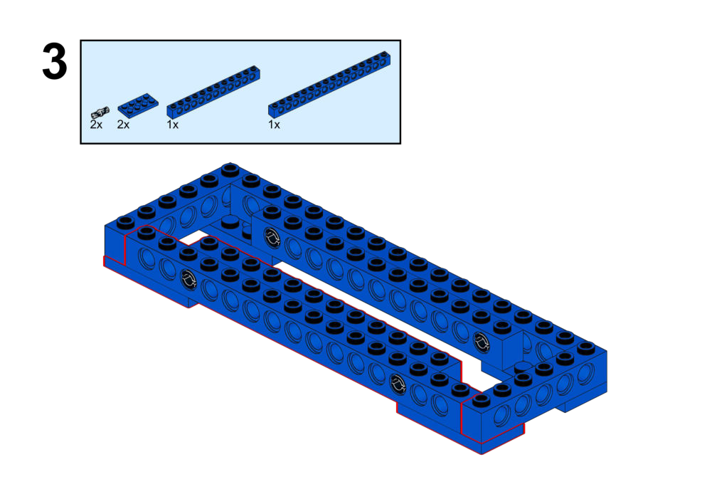
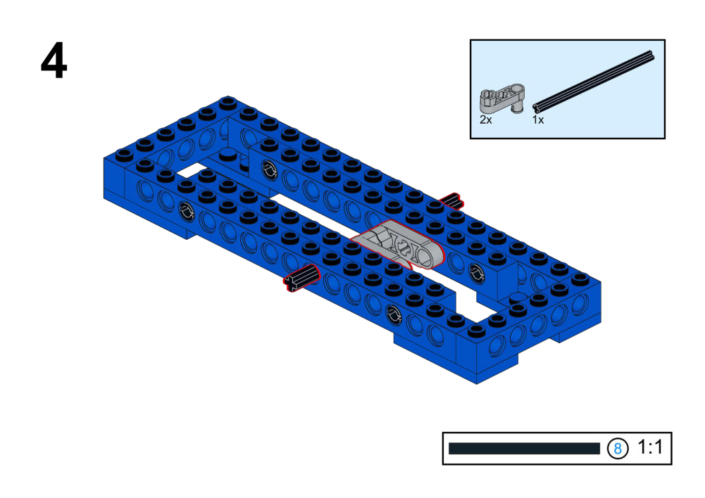
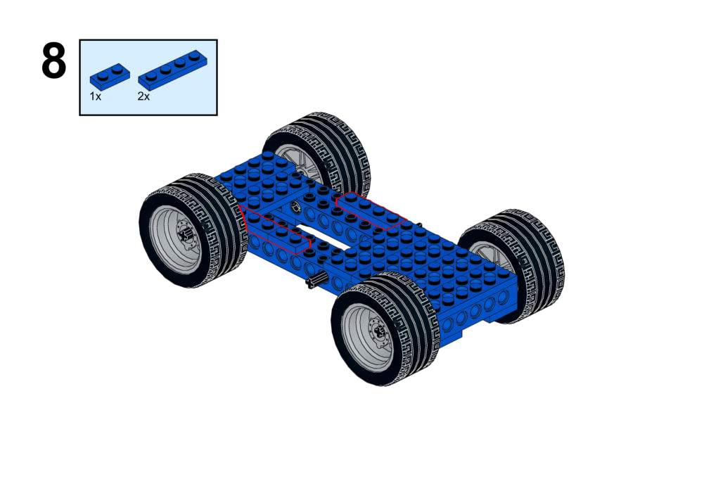
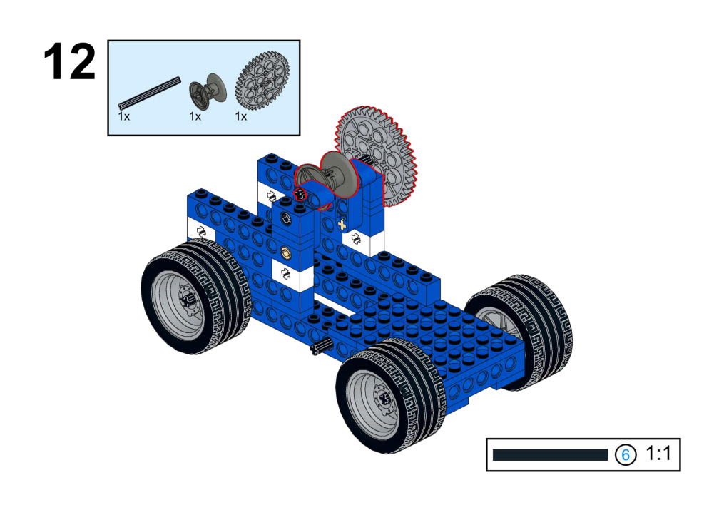
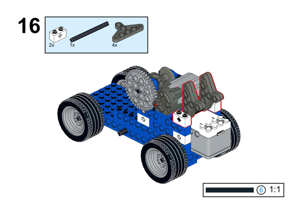
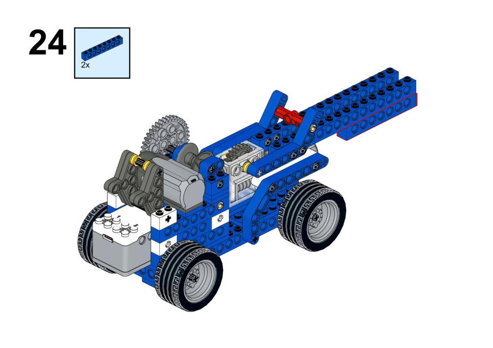
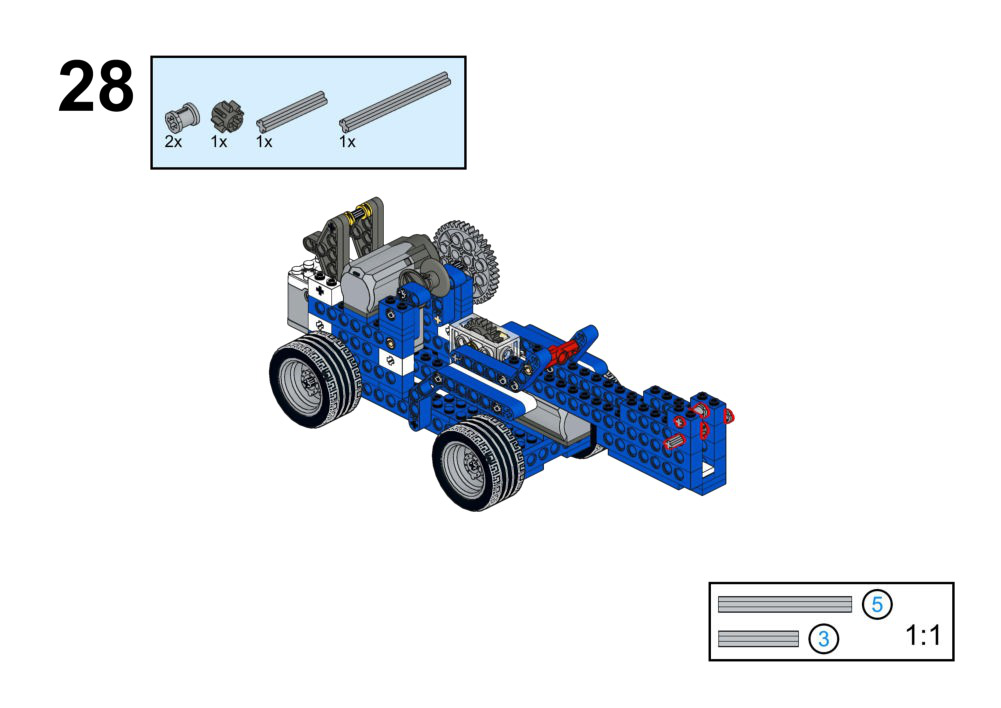
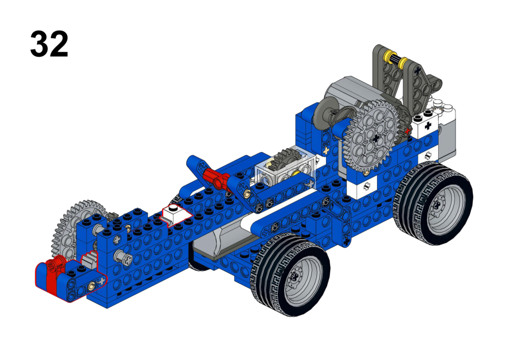
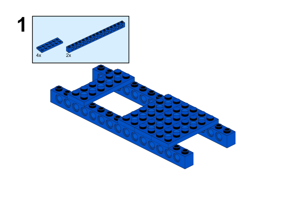
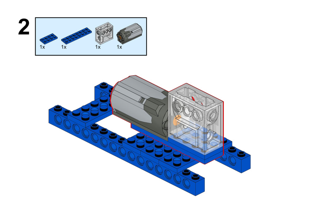
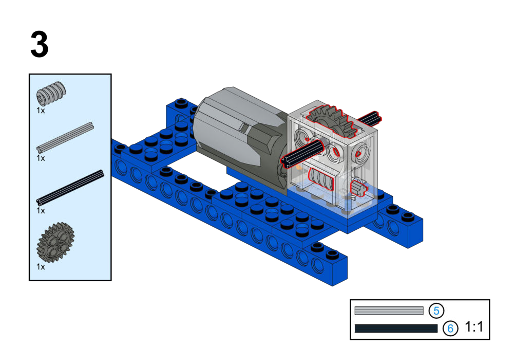
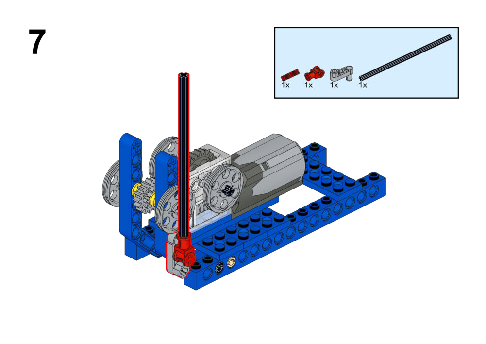
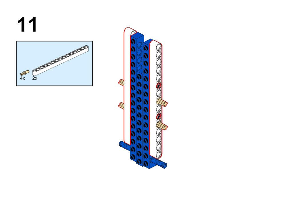
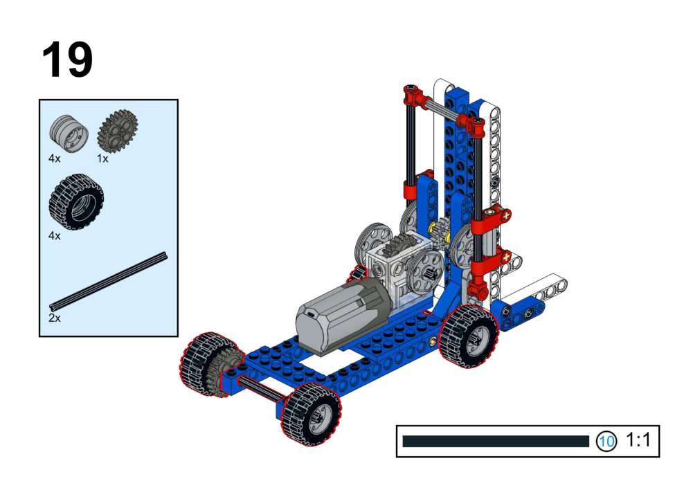
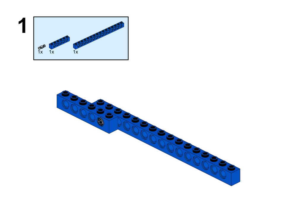
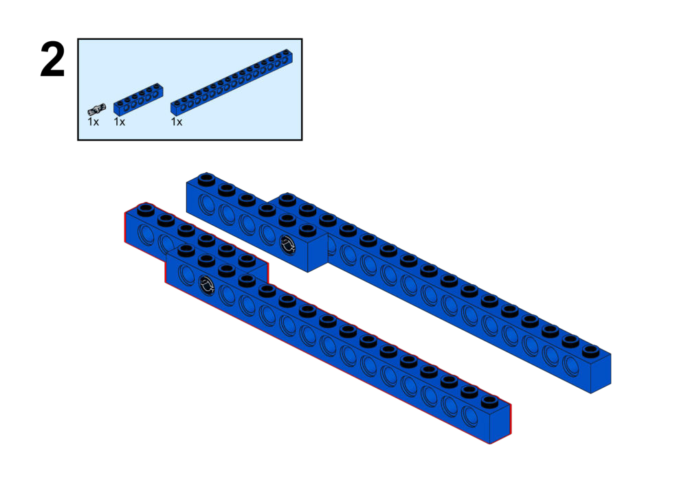
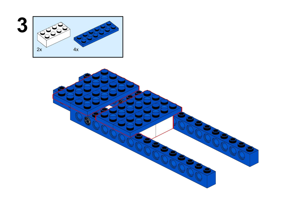
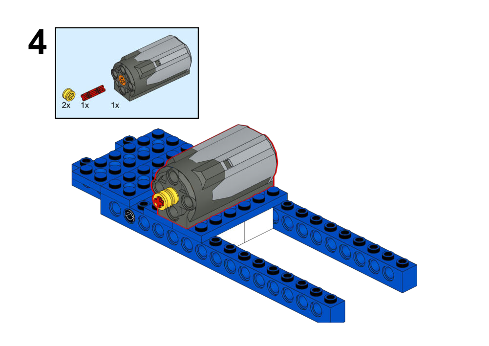
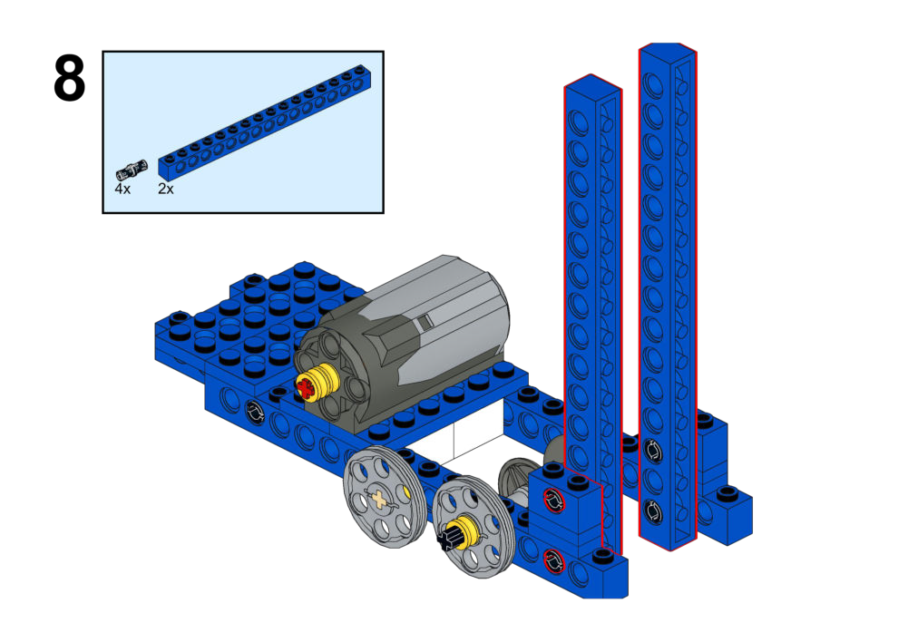
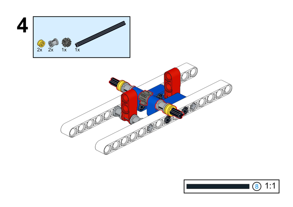
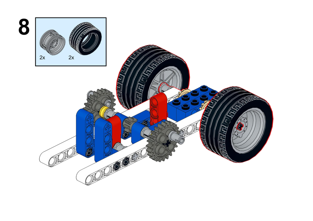
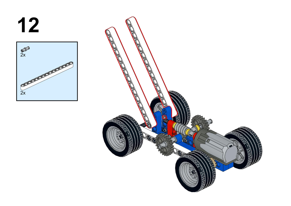
Assembly Instructions
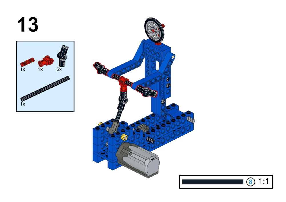
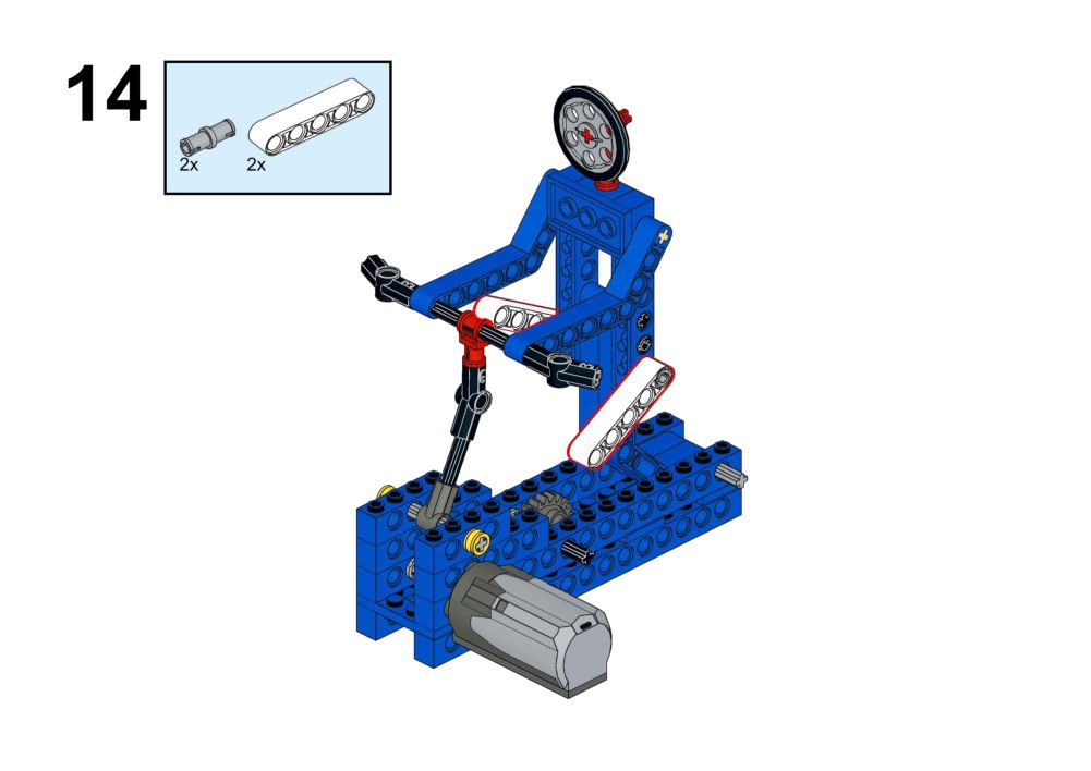
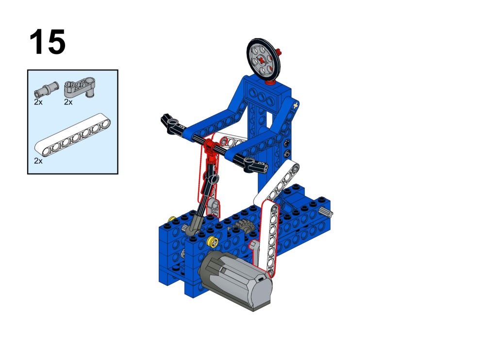
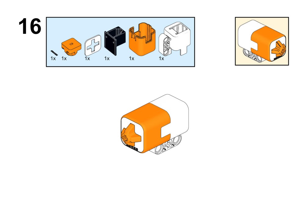
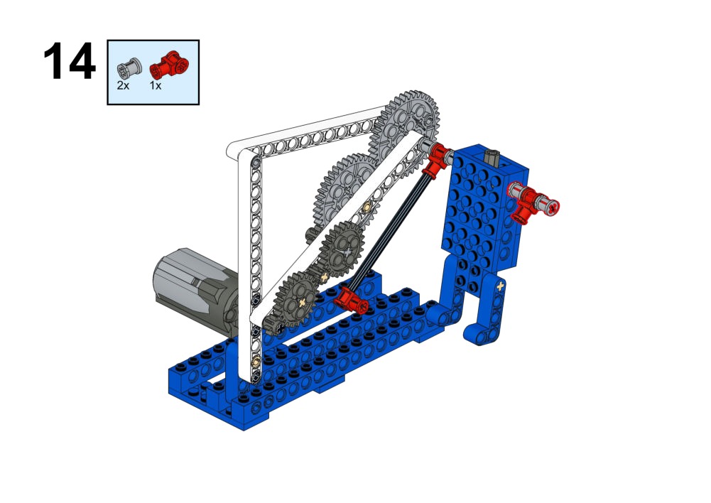
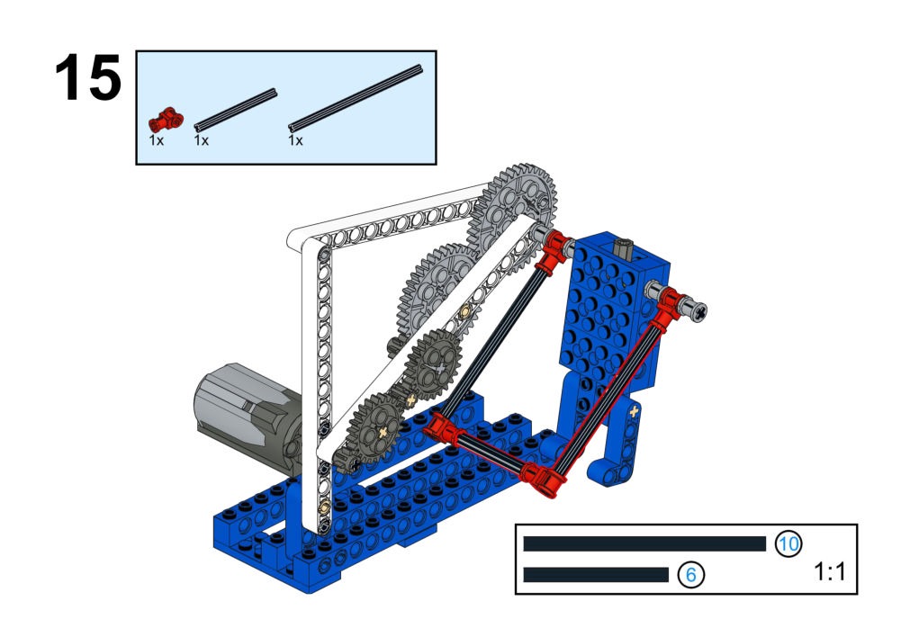
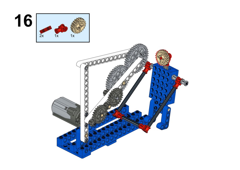
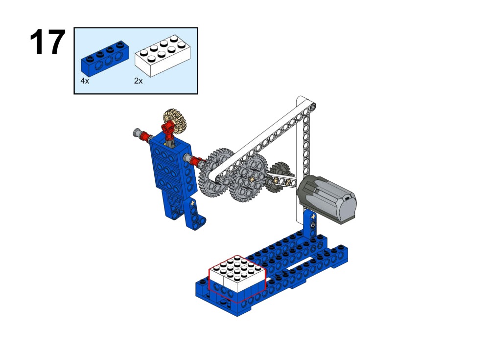
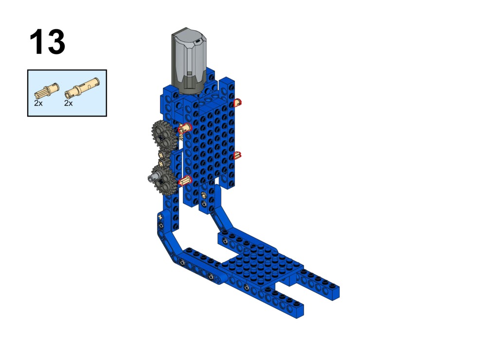
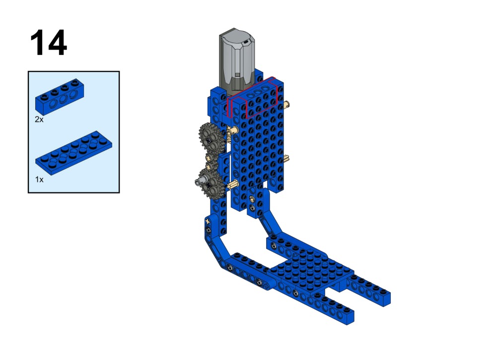
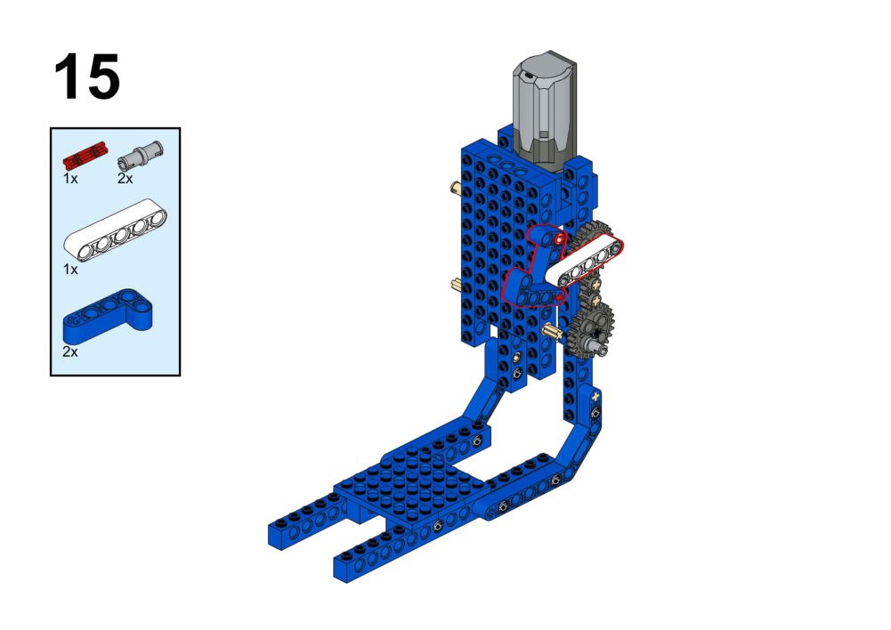
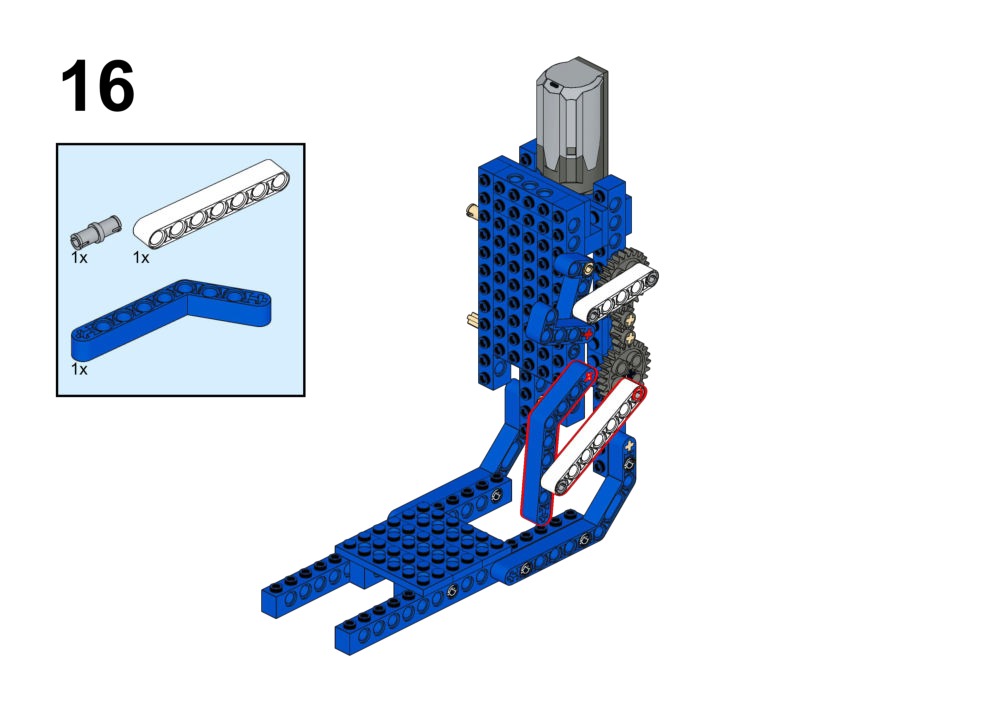
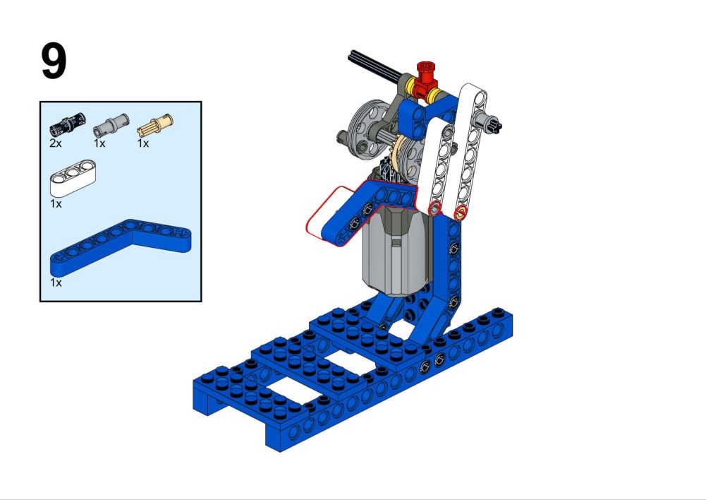
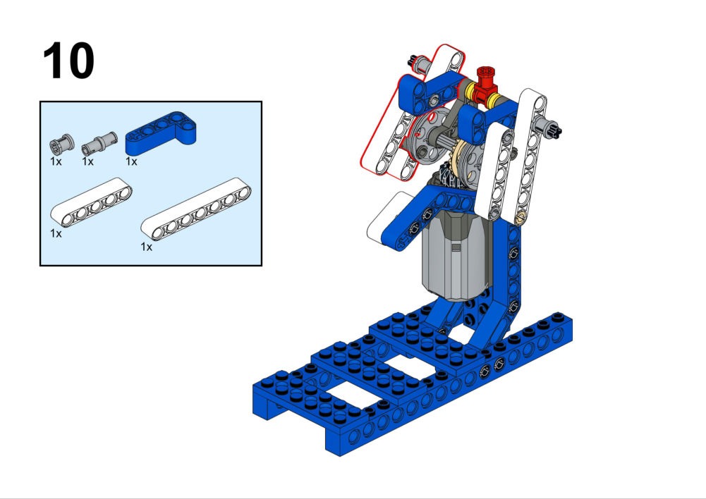
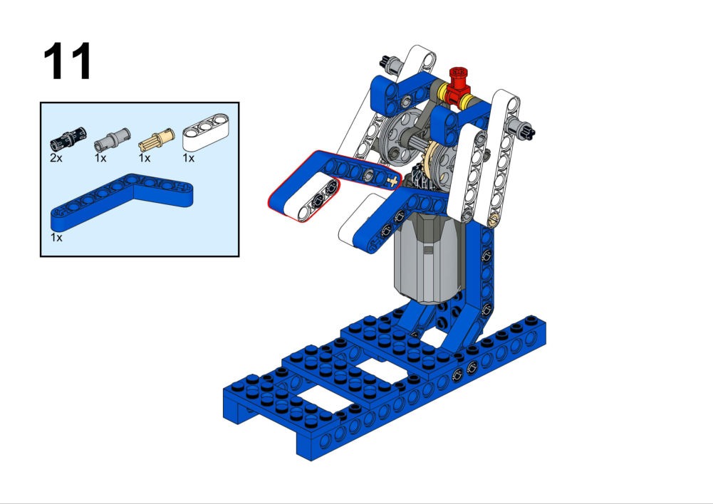
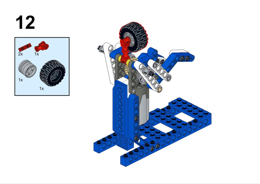
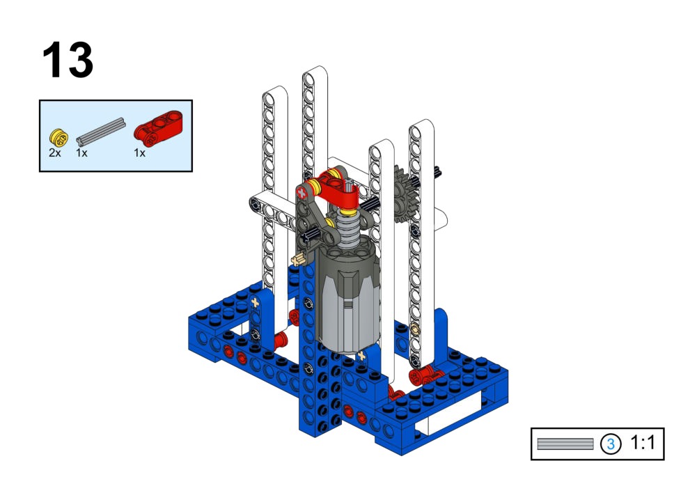
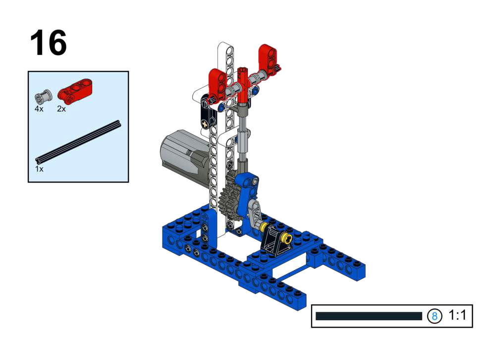
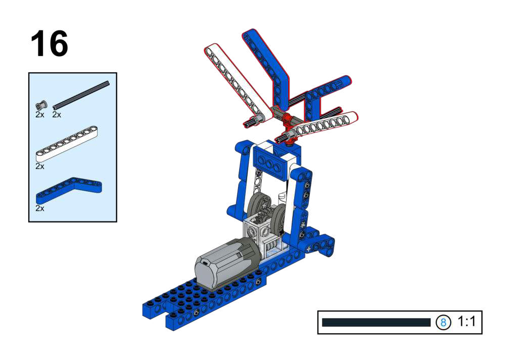
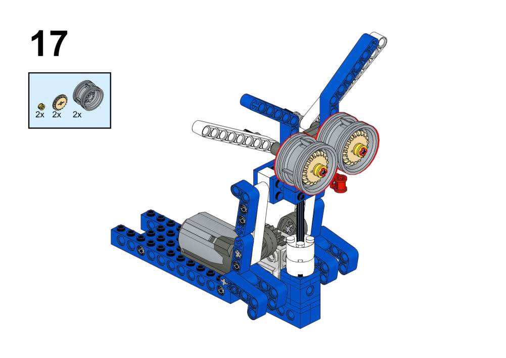
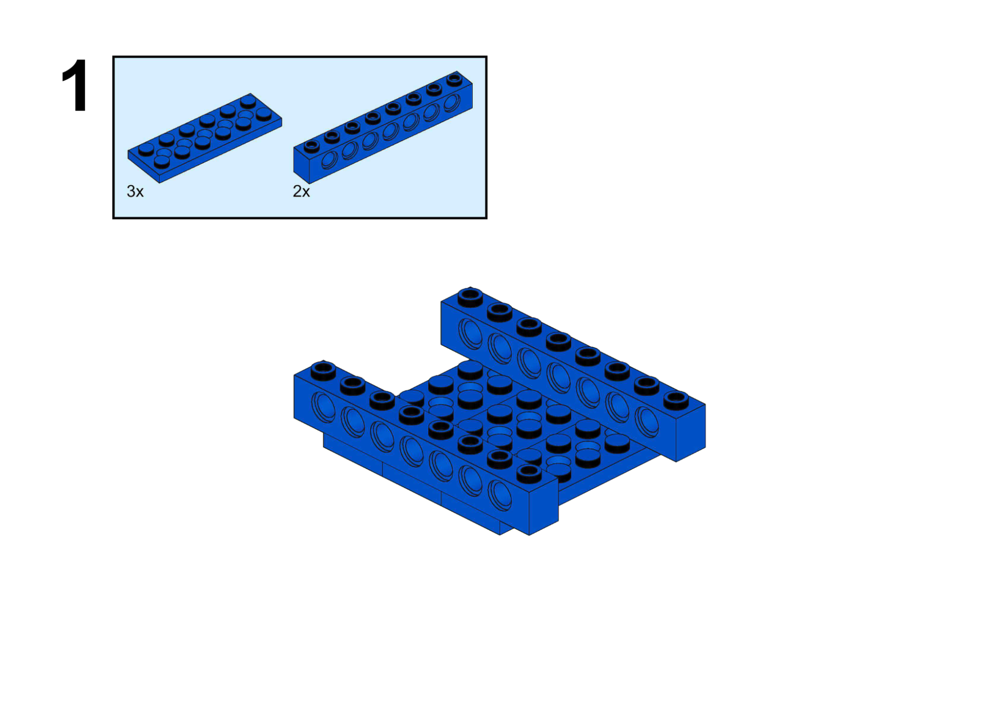
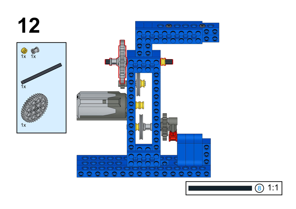
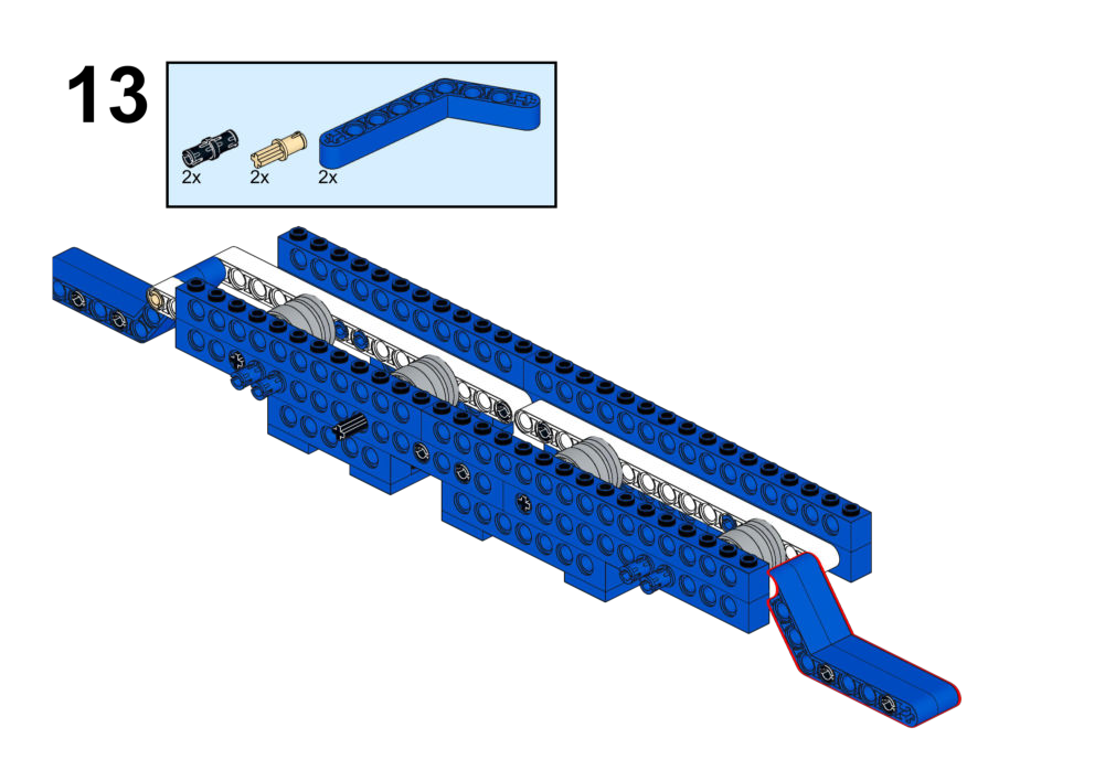
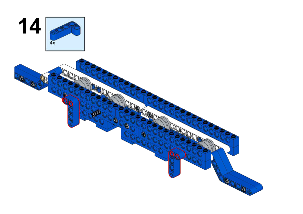
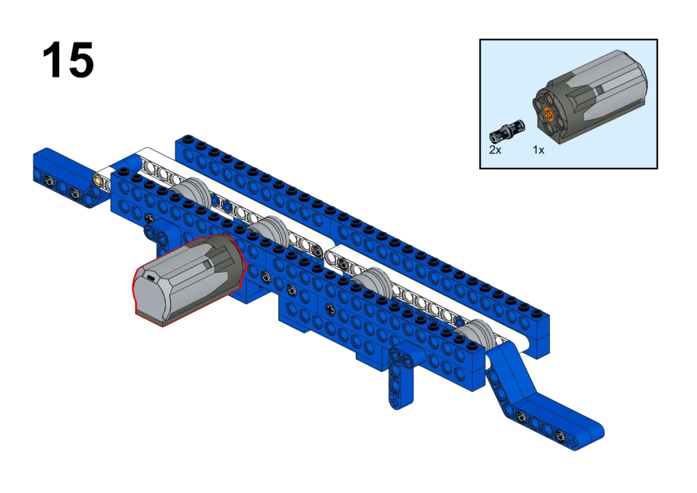
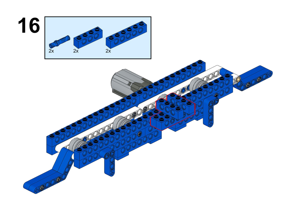
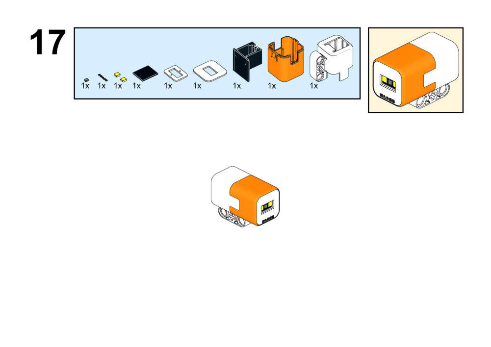
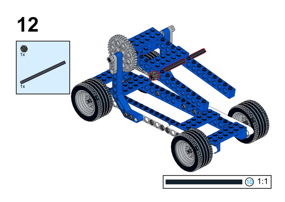
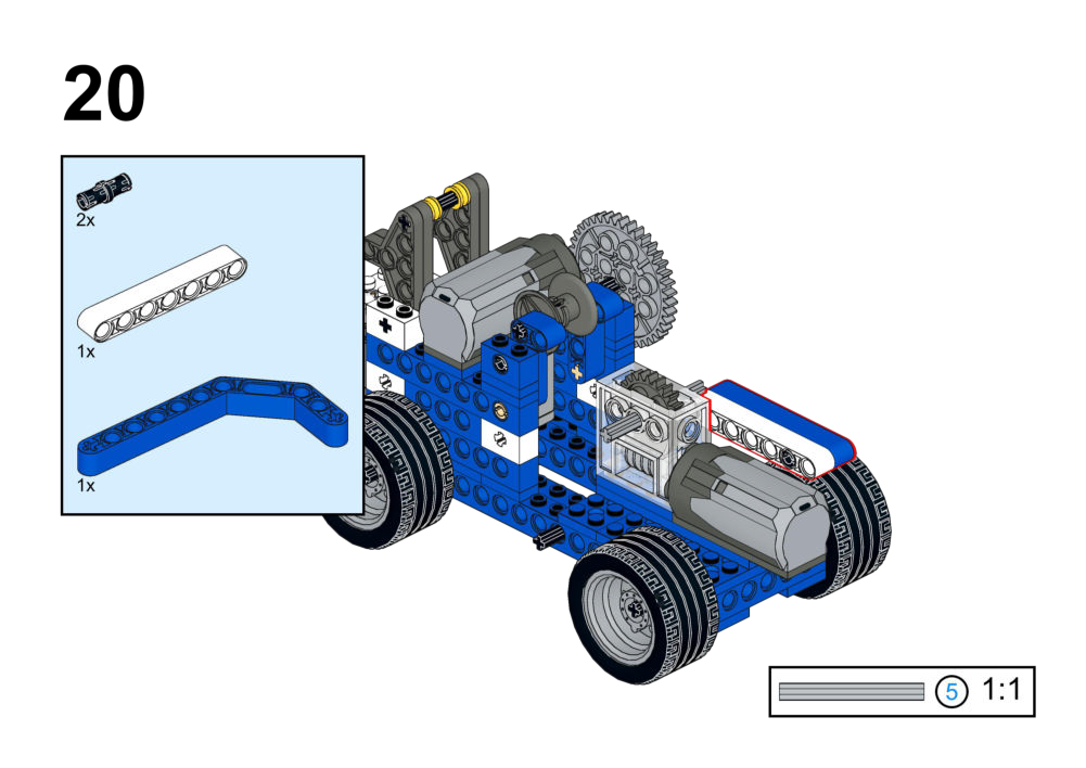
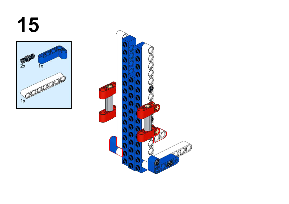
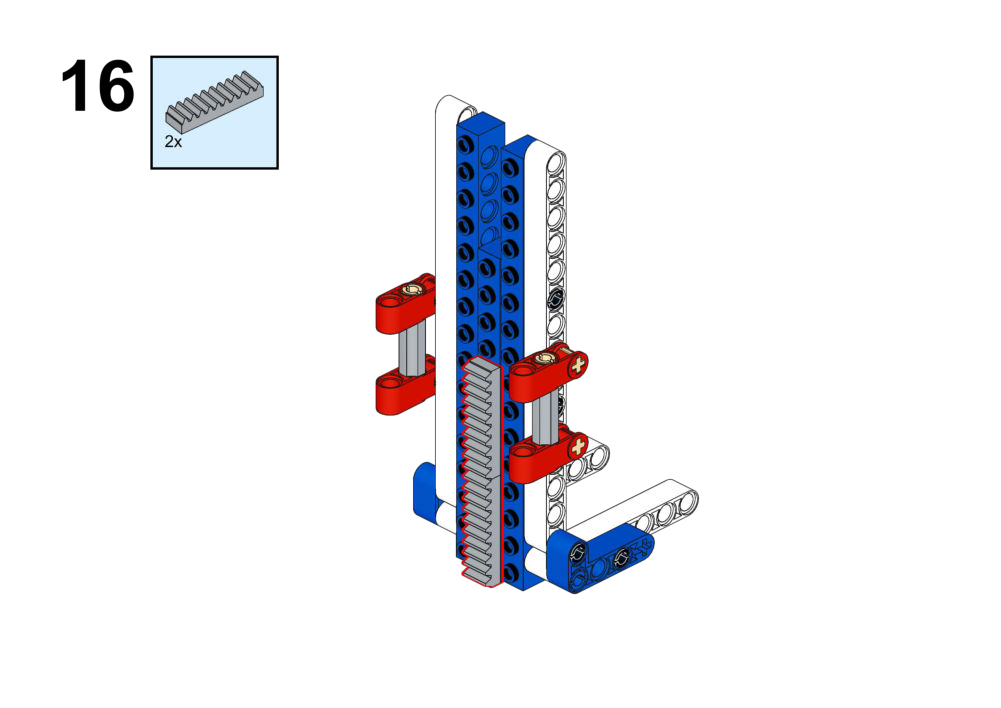
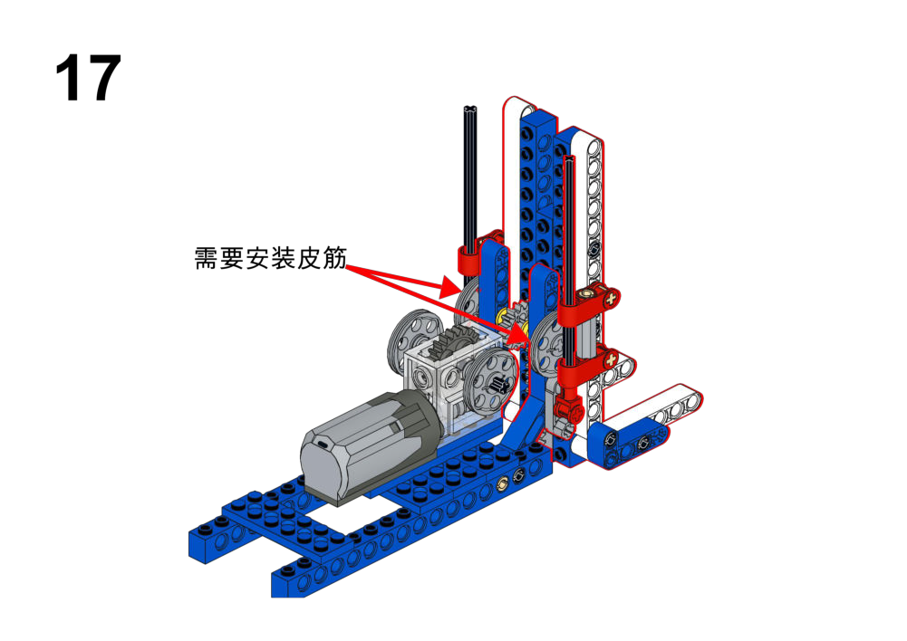
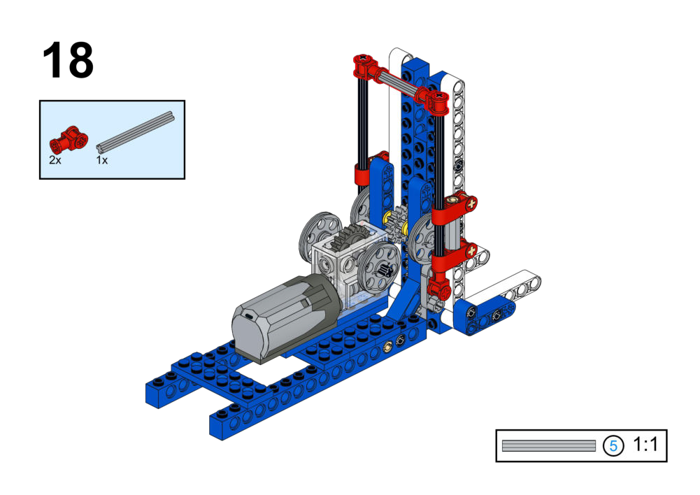
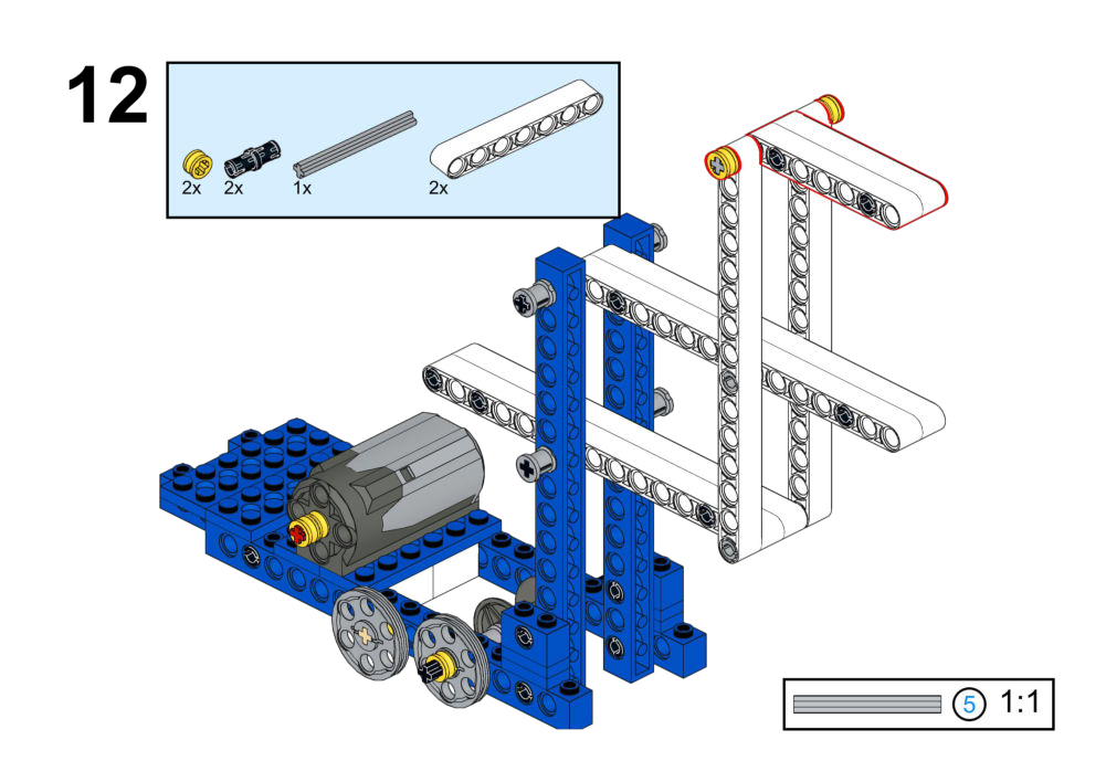
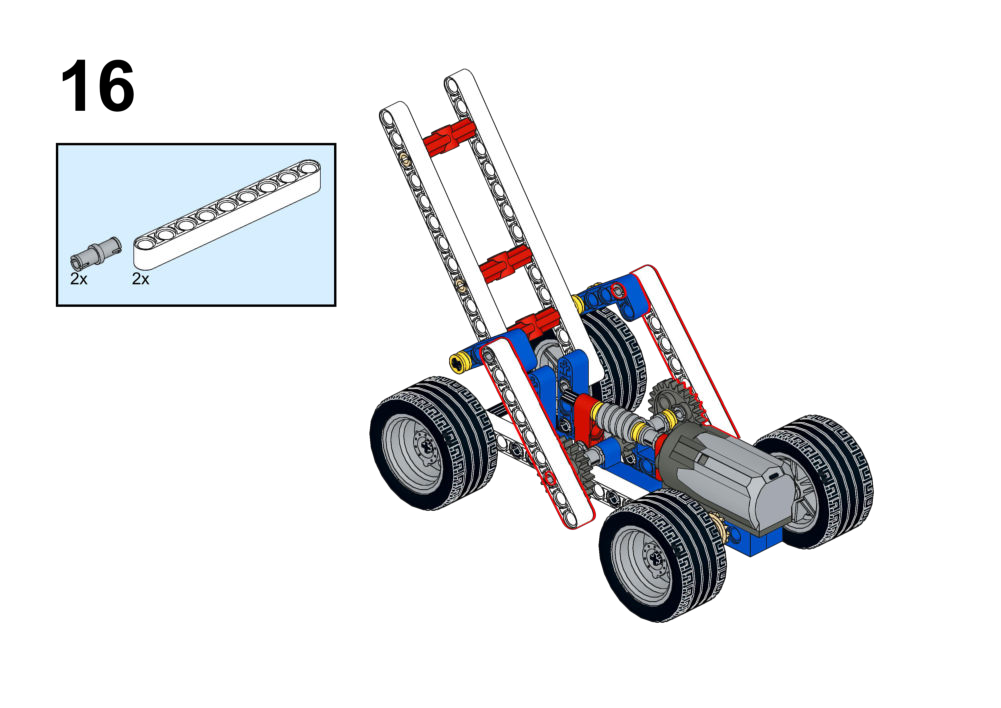
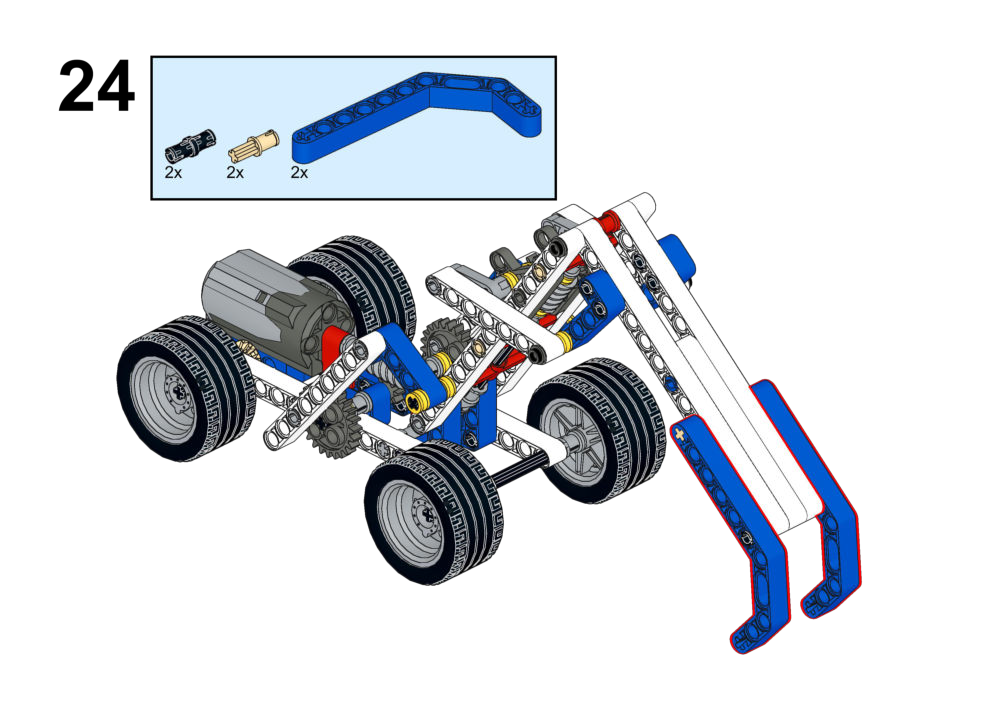
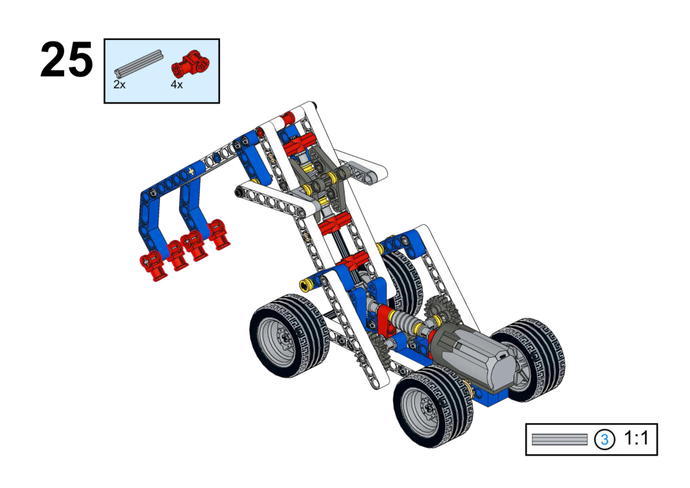
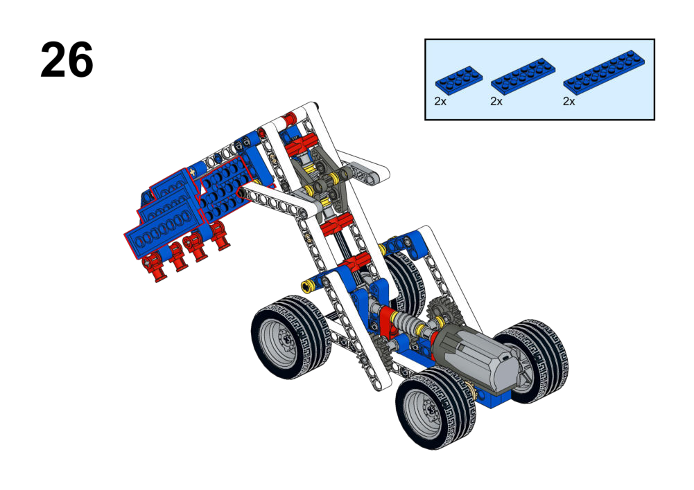
Each exercise has a set of instructions attched on how to assemble the structure, in the "View Assembly Instructions" box.
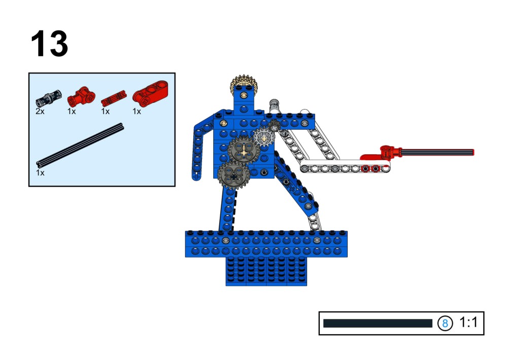
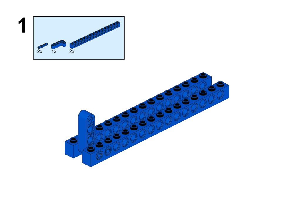
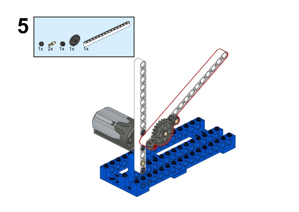
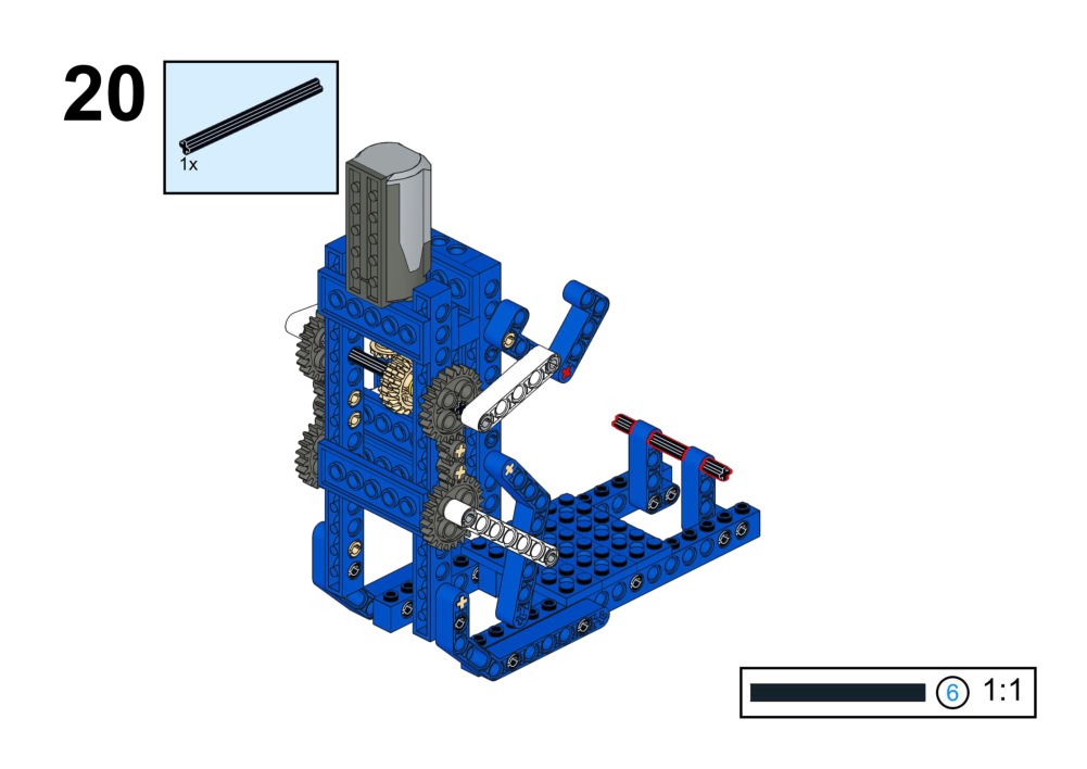
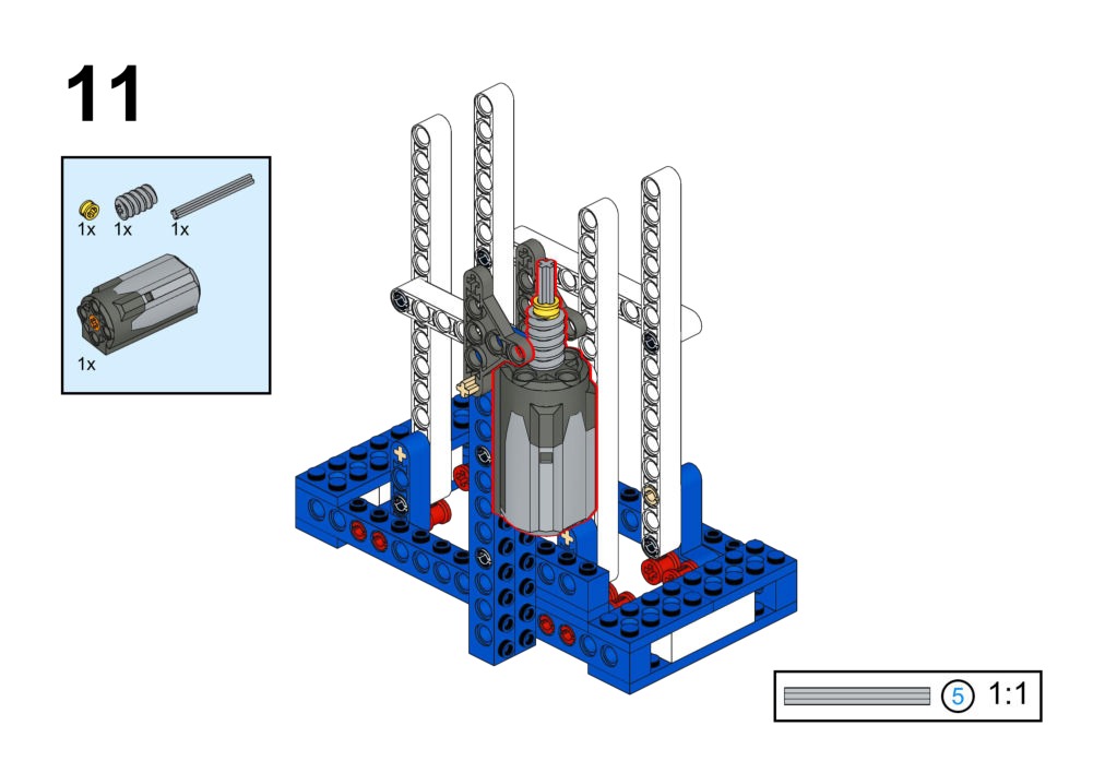
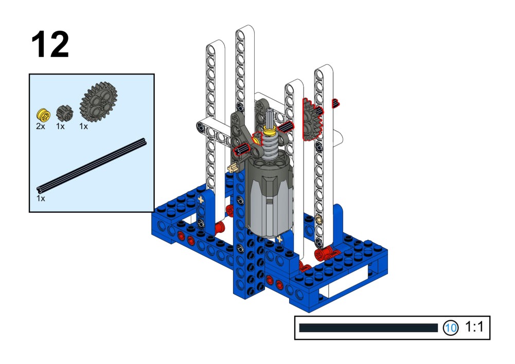
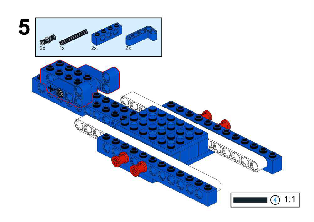
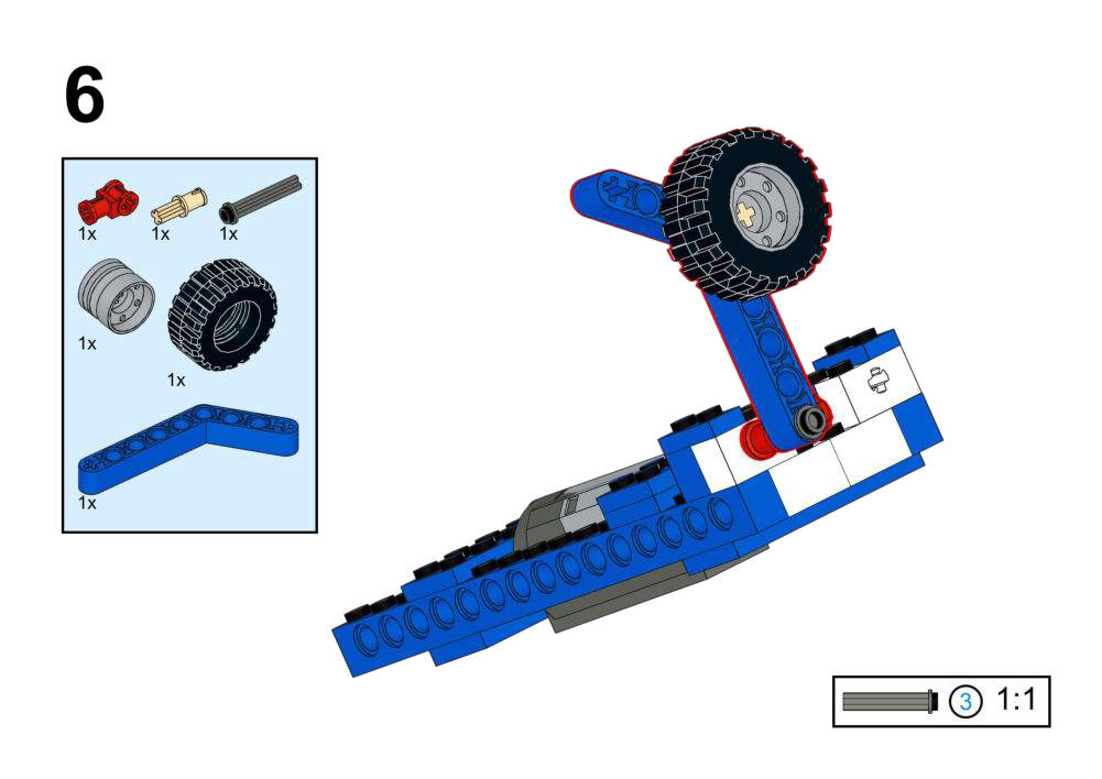
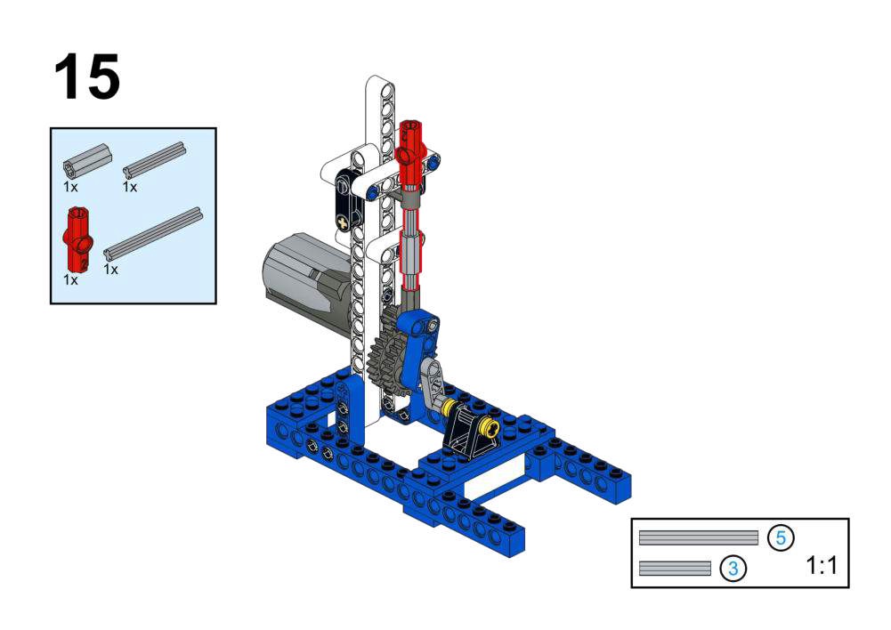
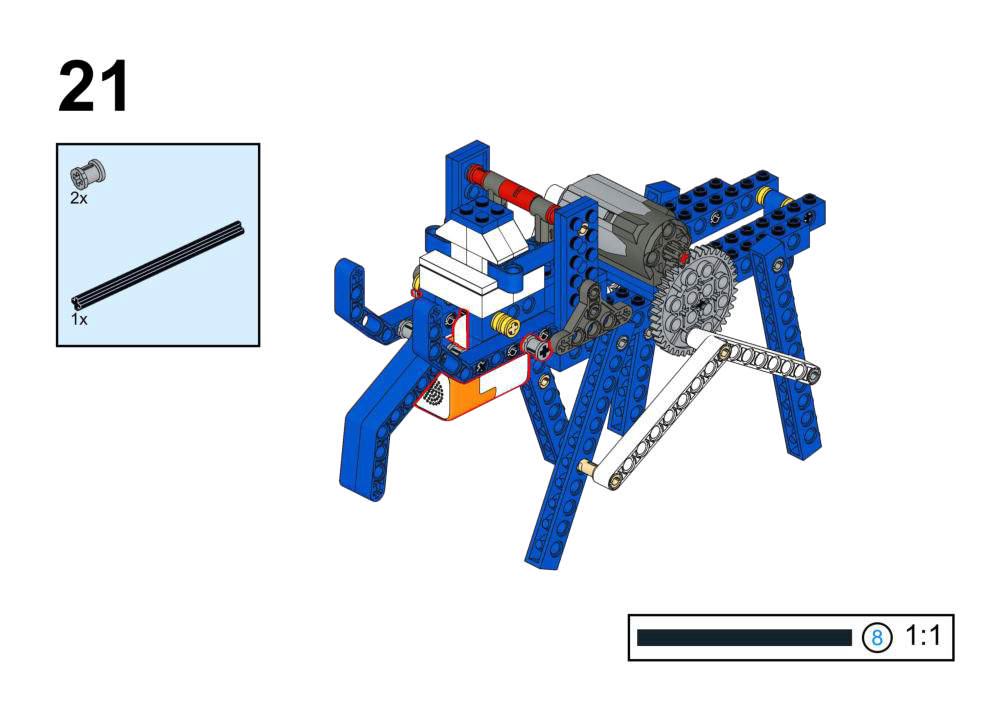
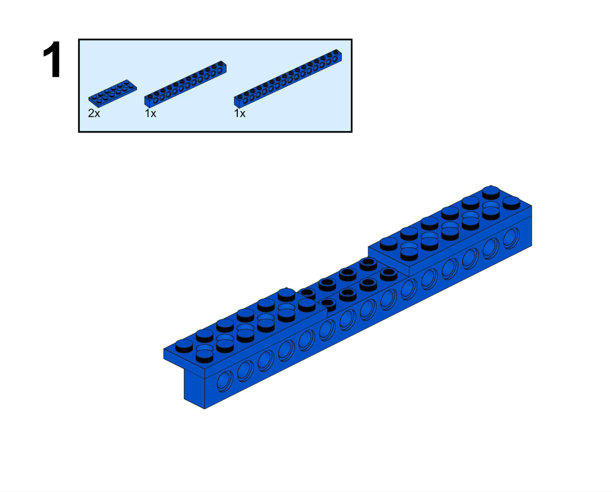
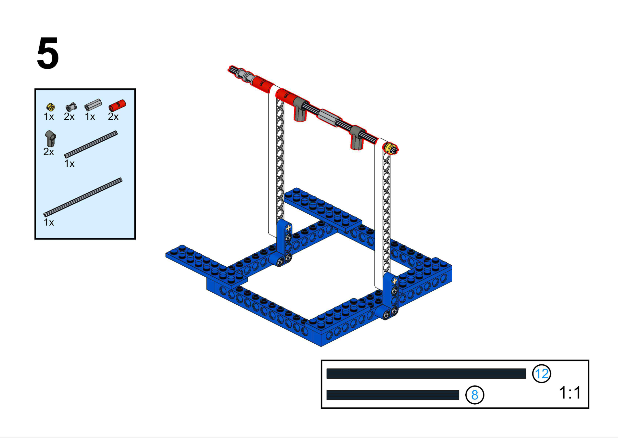
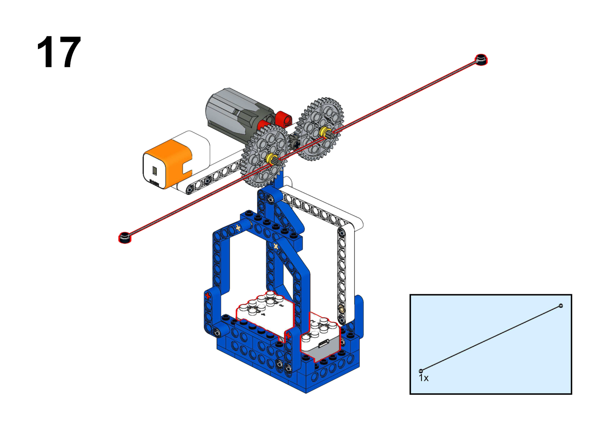
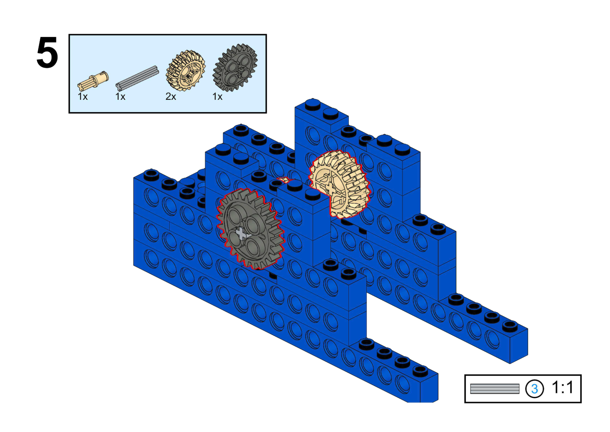
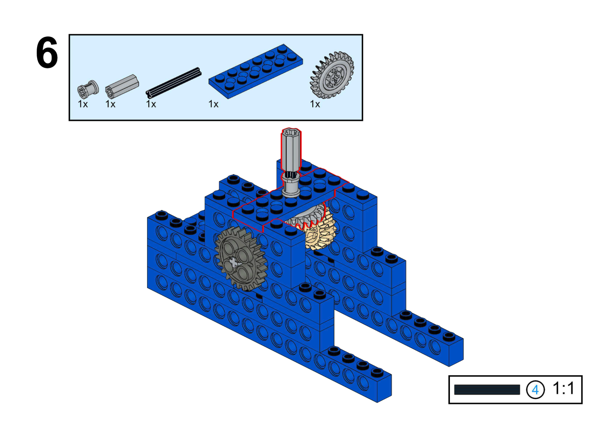
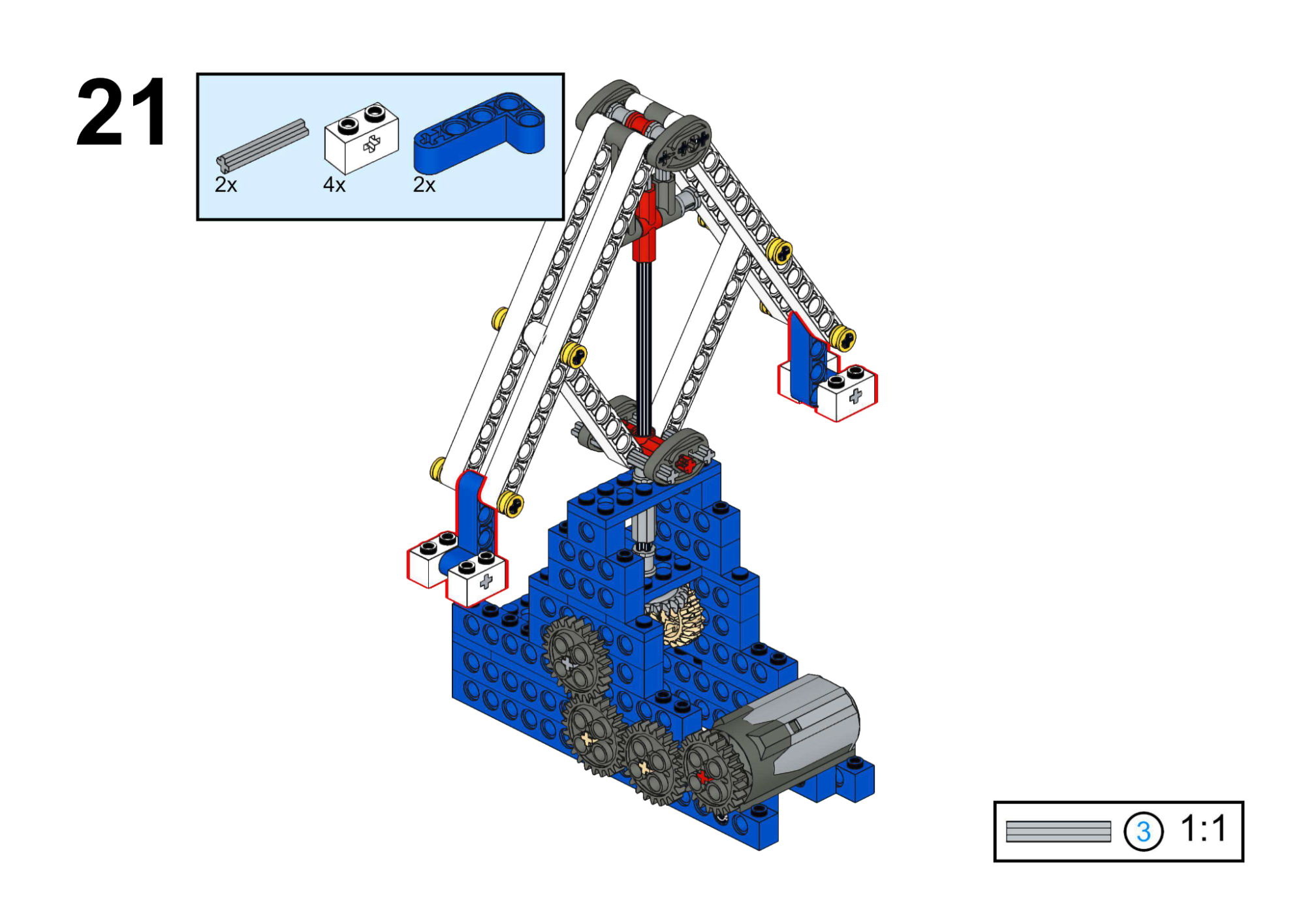
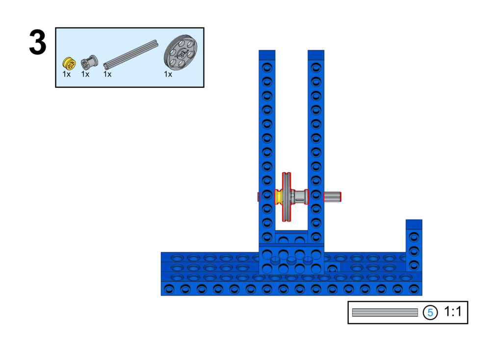
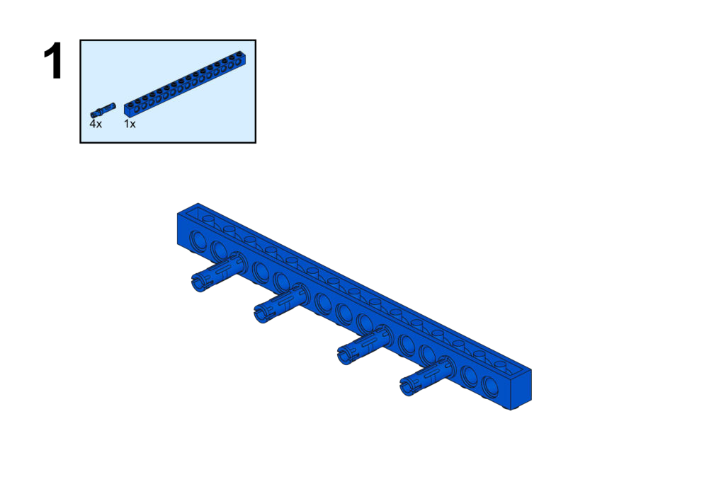
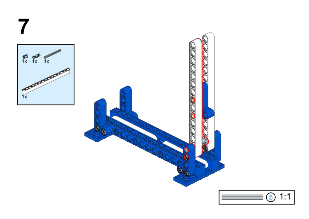
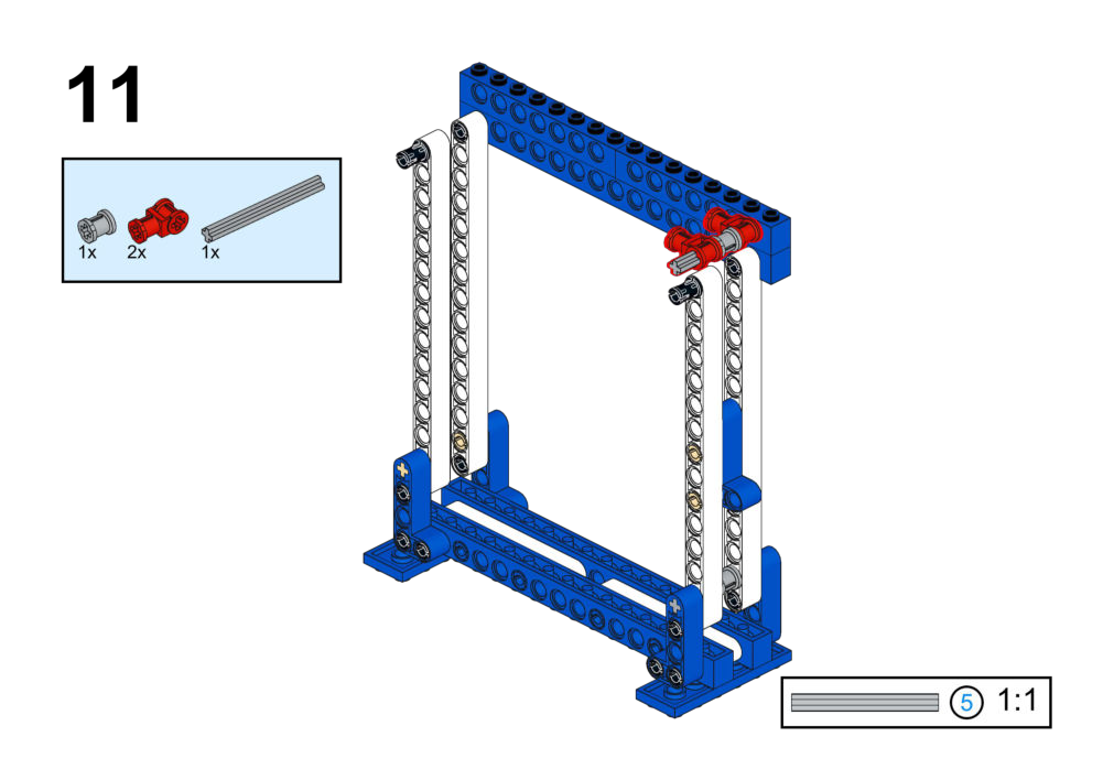
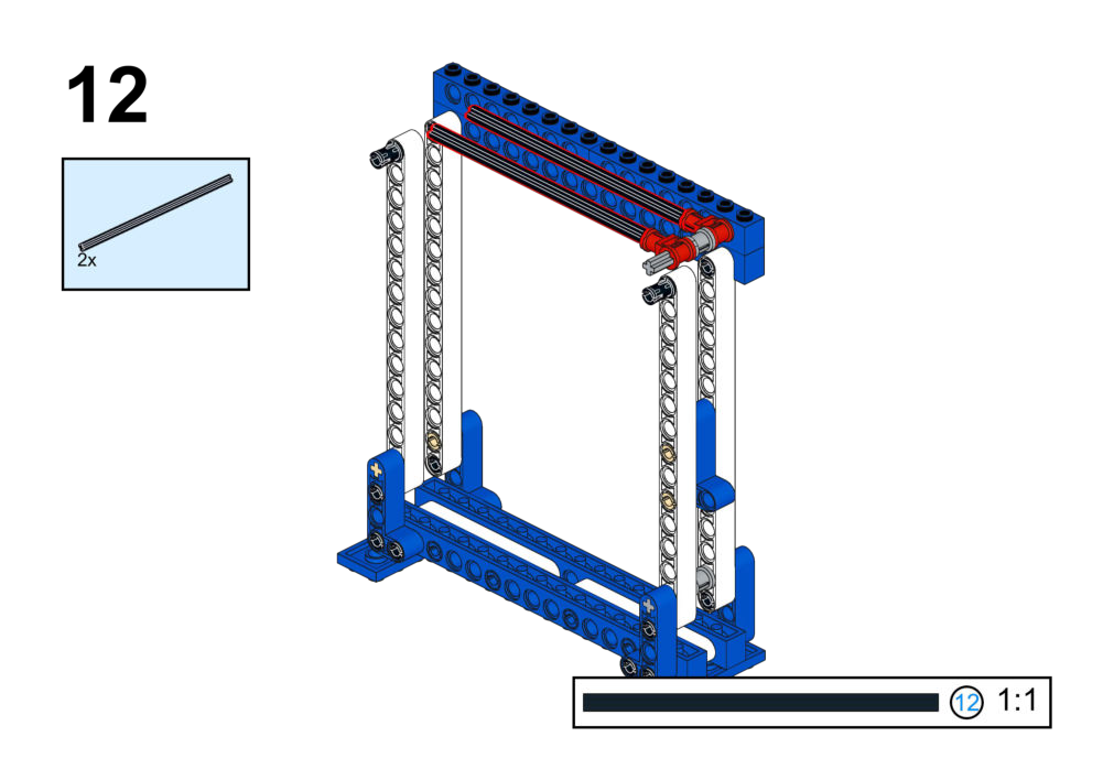
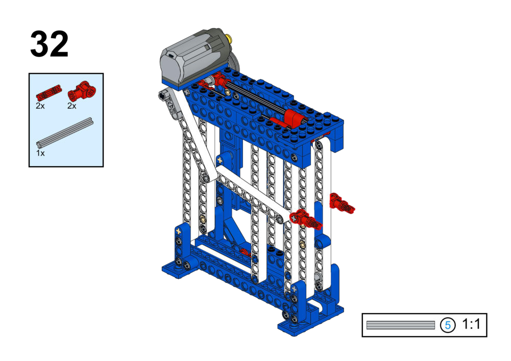
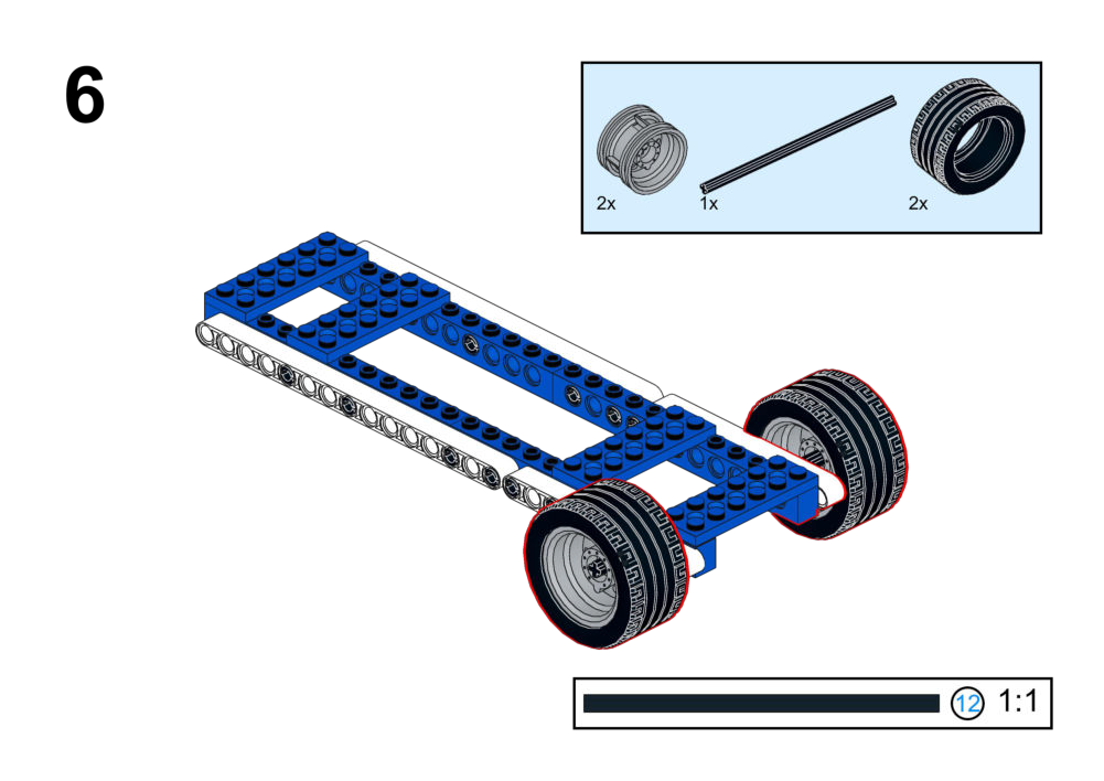
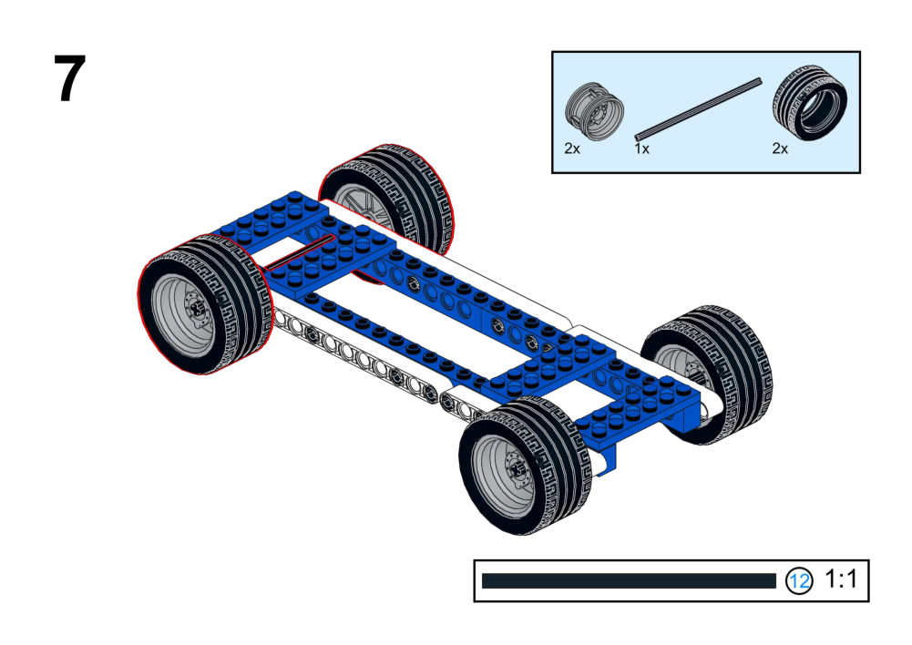
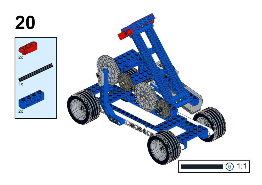
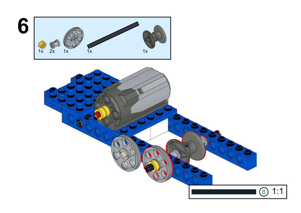
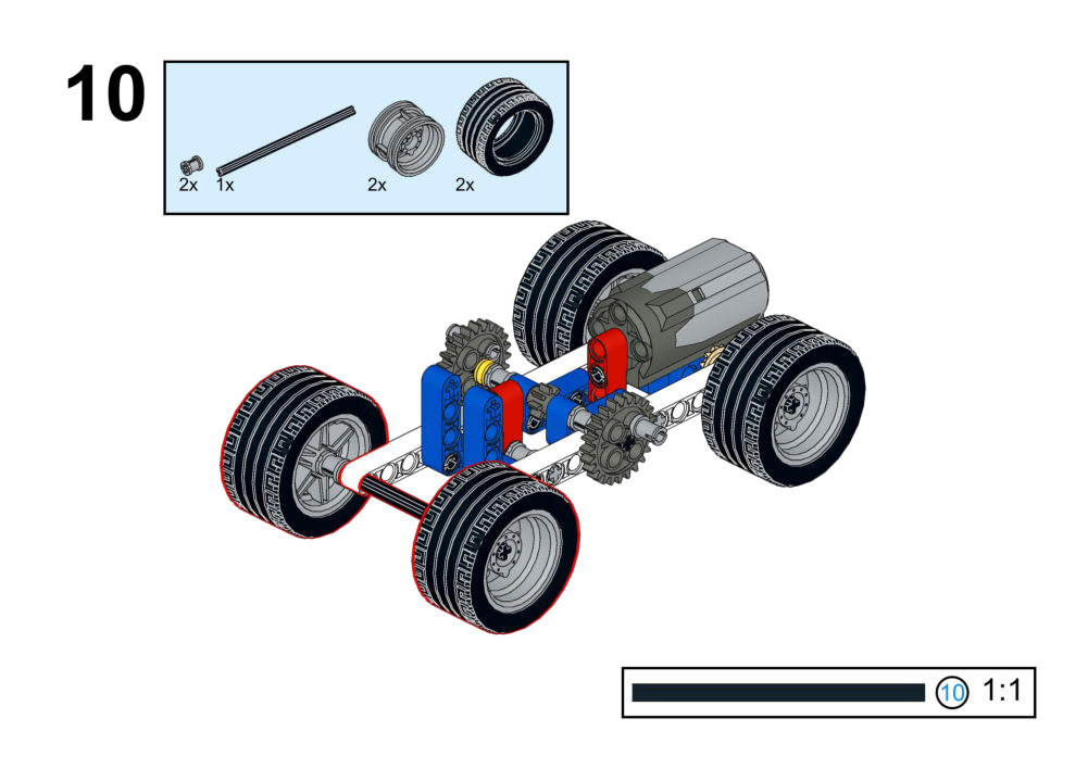
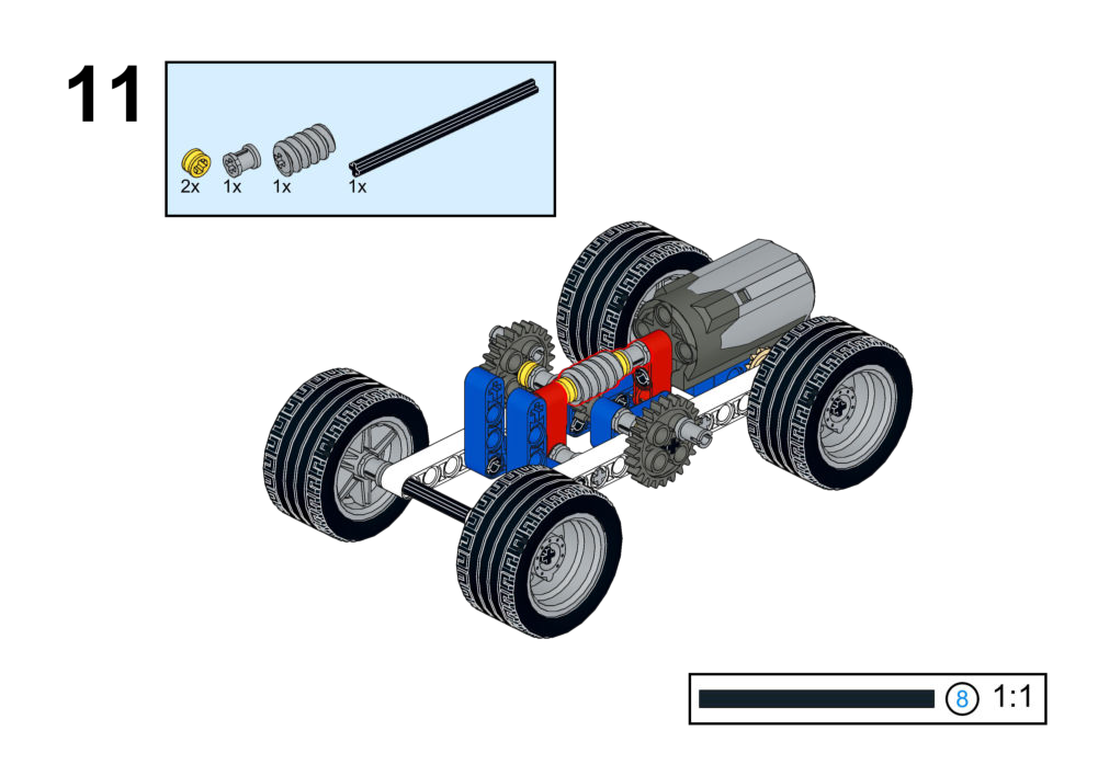
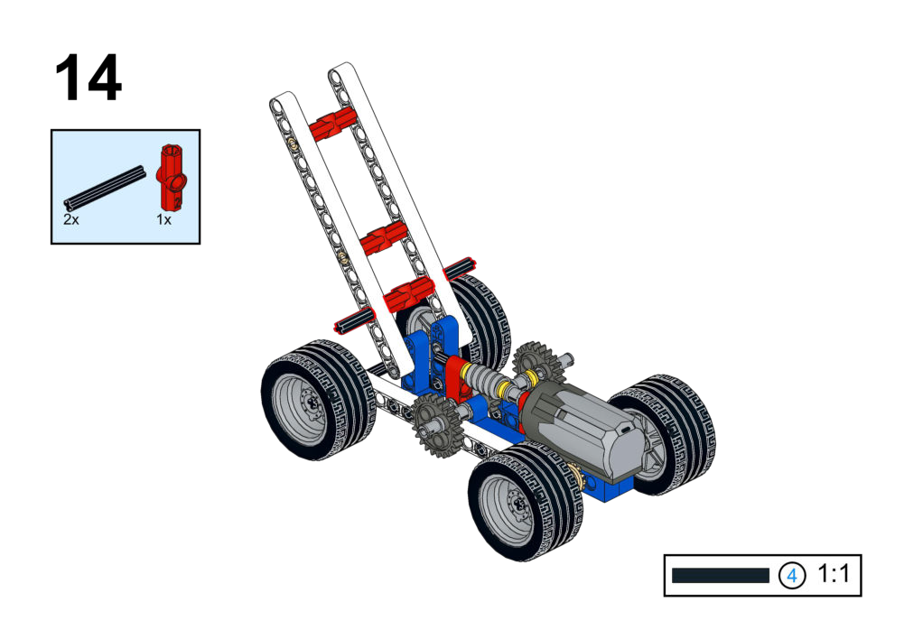
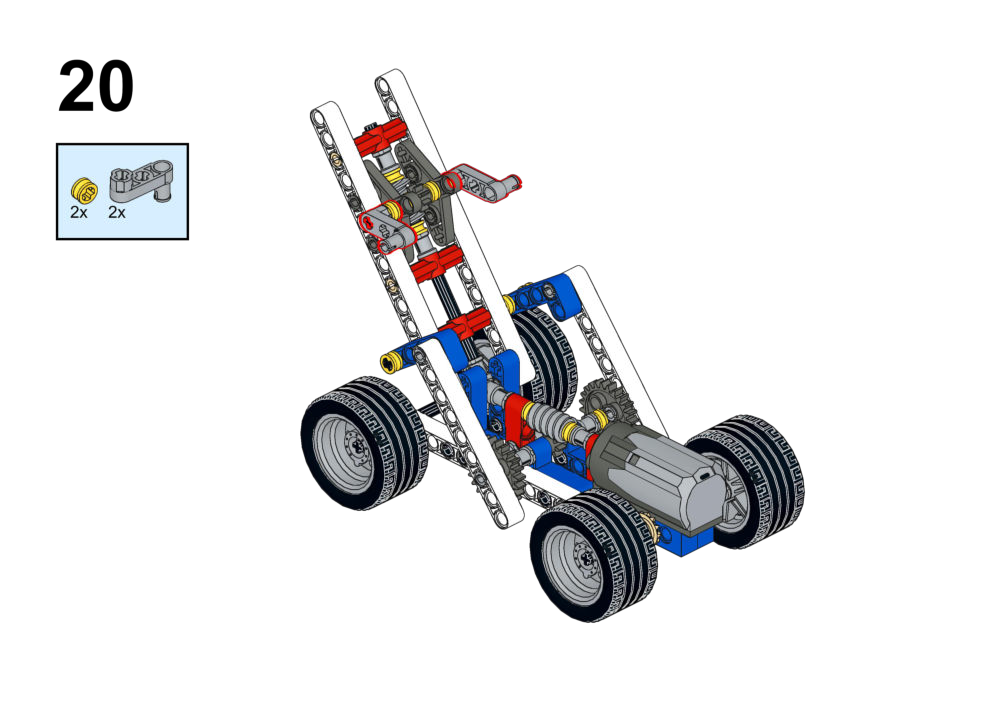
These instructions will sometimes contain a scale reference, like the one below:

Note that these do not indicate length in standard units such as centimeters or inches, but are used to scale parts relative to each other.
1. Sports Series (Human Motion)
Focus: Mechanisms that simulate human fitness movements and variable control logic.
Goal
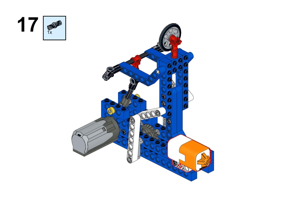
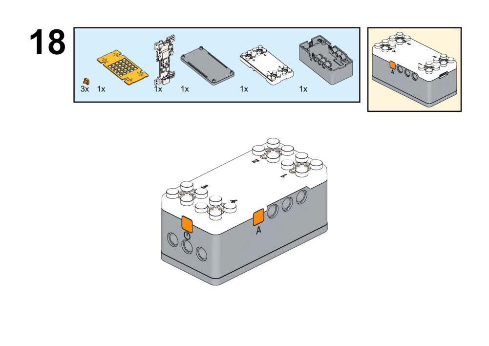
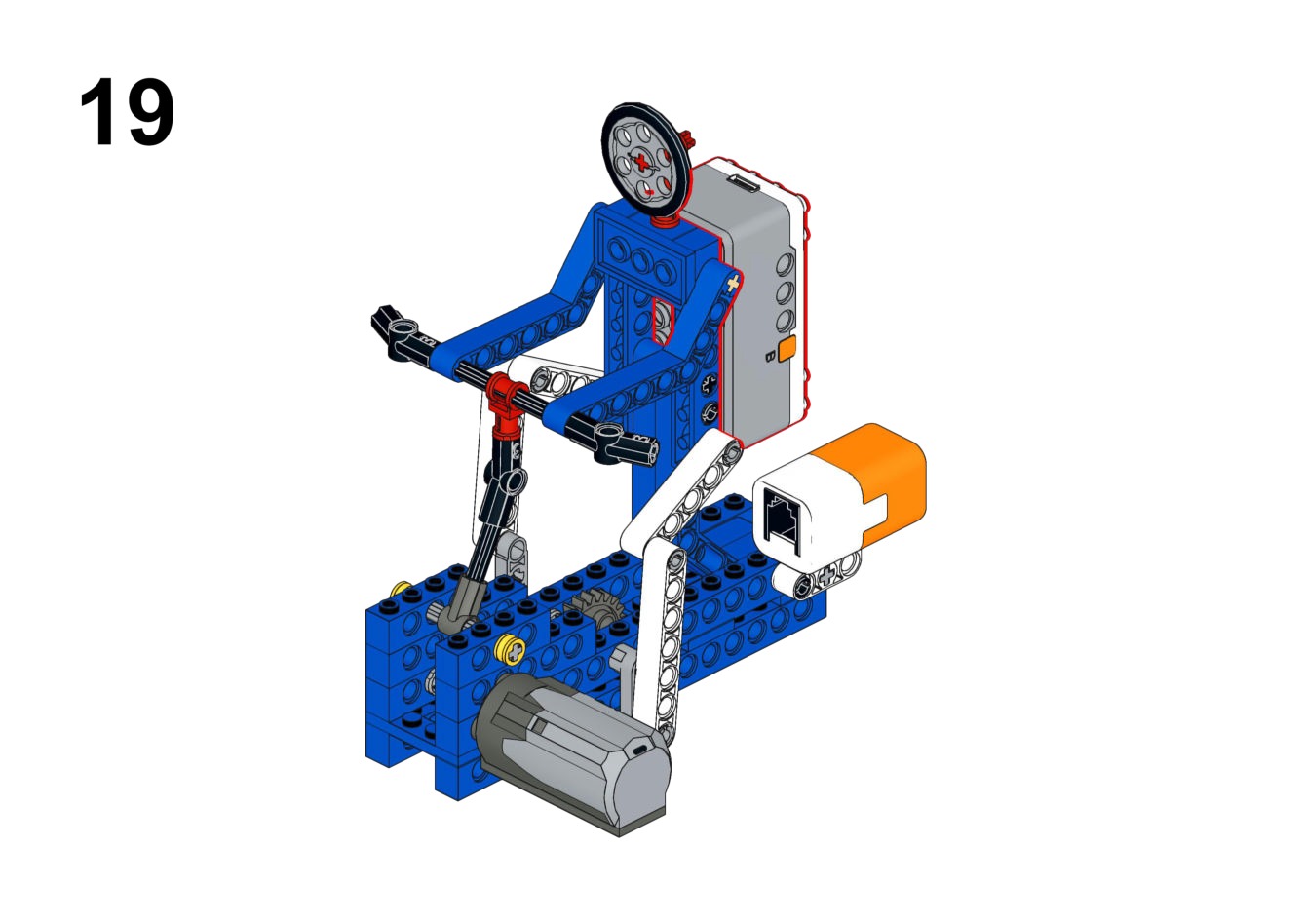
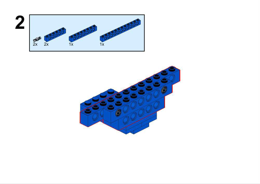
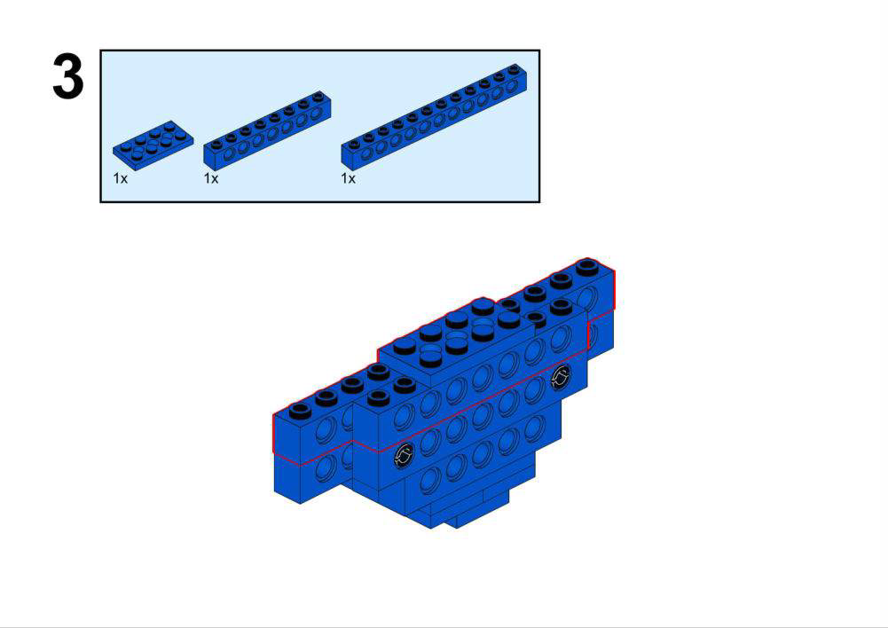
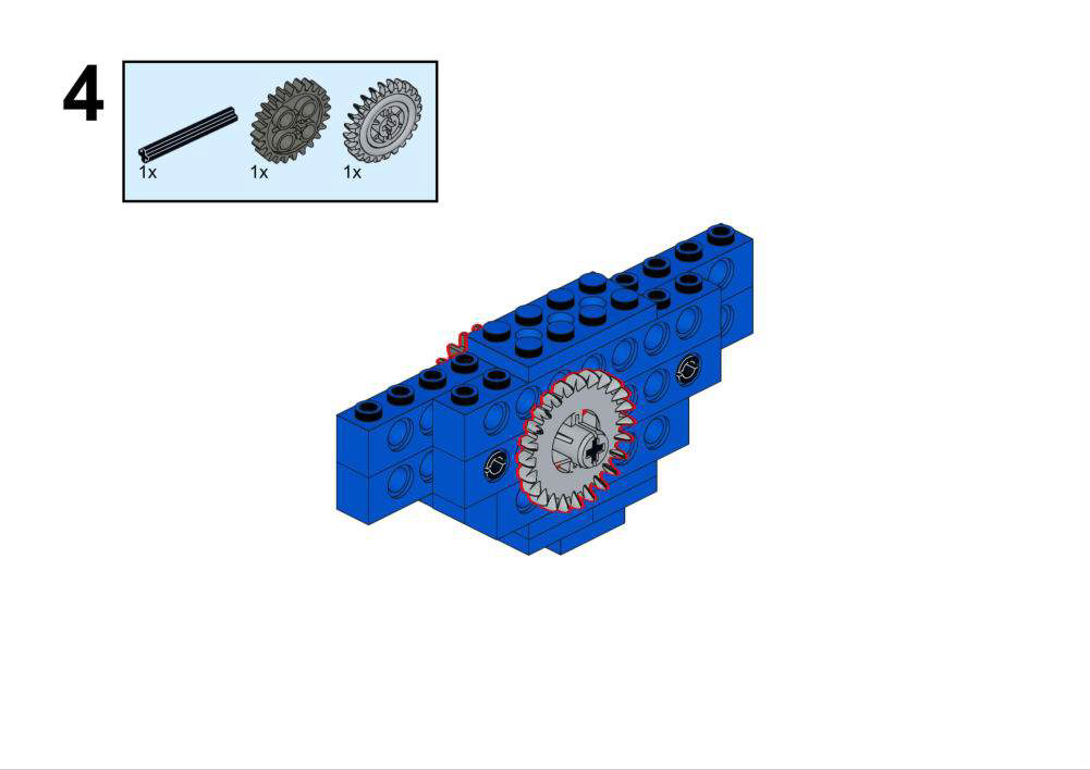
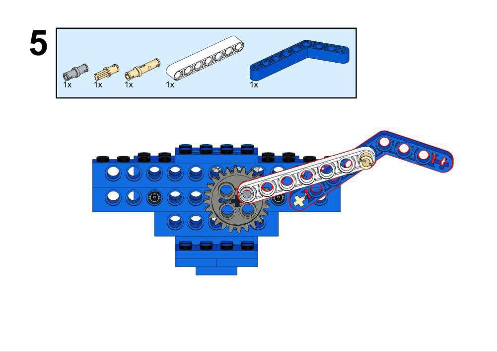
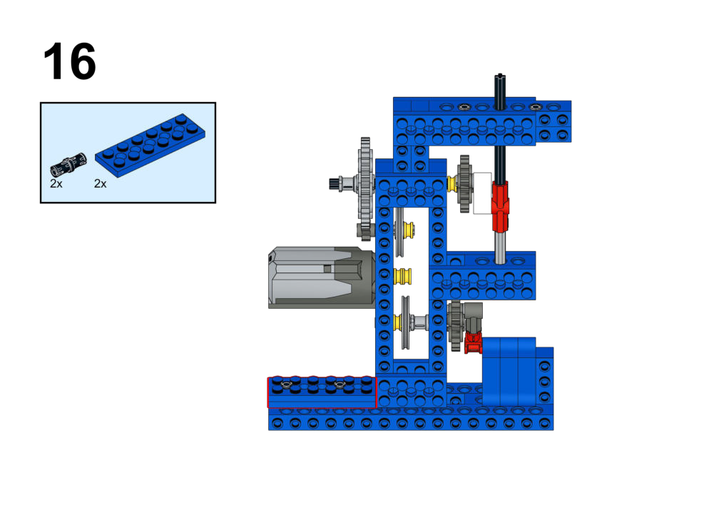
Simulate a spinning bike where users can adjust the resistance "gear" using a touch sensor.View Assembly Instructions
Hardware & Wiring
- Motor (Drive): Port 2
- Touch Sensor: Port 1
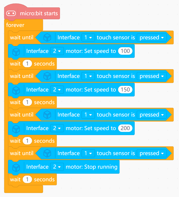
What You Do in Mind+
- Create variable
Gear. - When Touch Sensor is pressed: Increase
Gear. - Map
Gearto motor speed (e.g., Gear 1 = 100, Gear 2 = 200).
View Completed Program
Goal
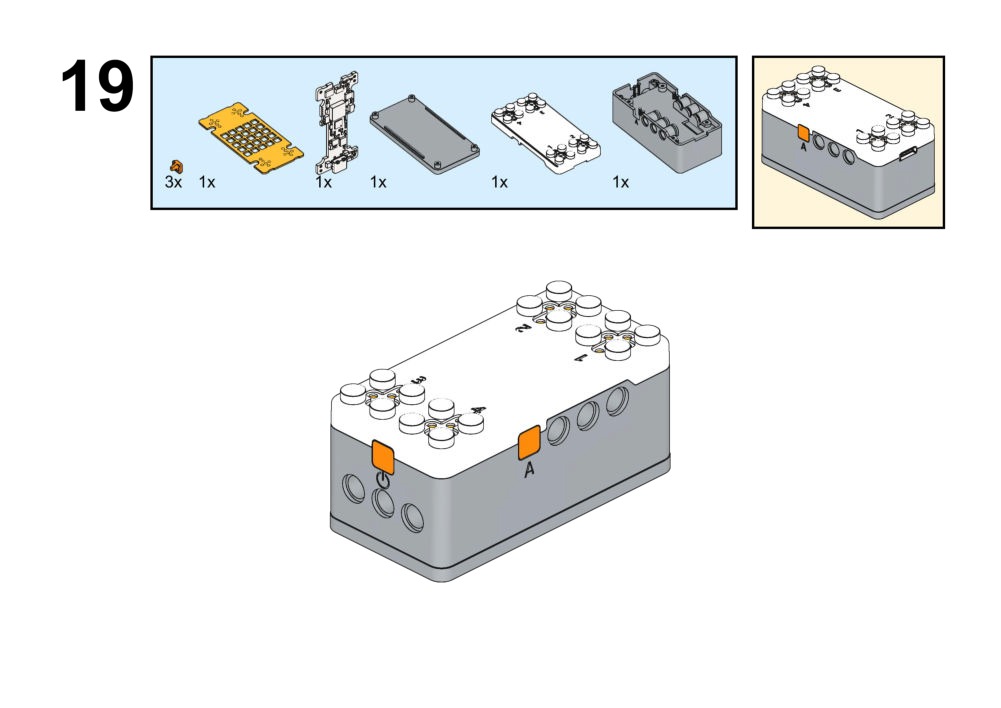
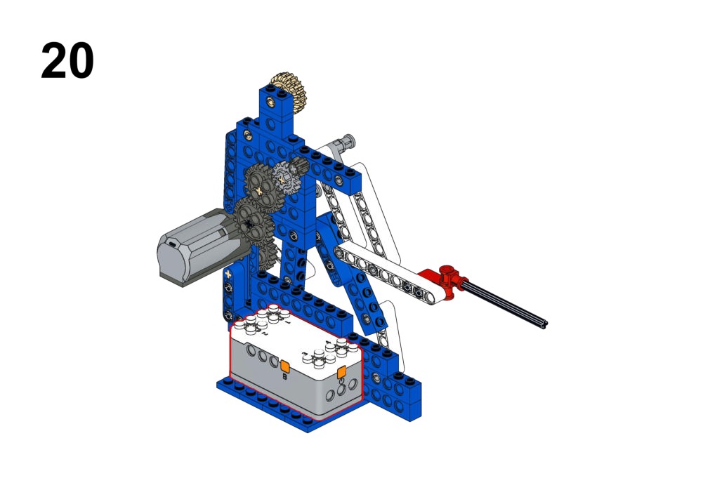
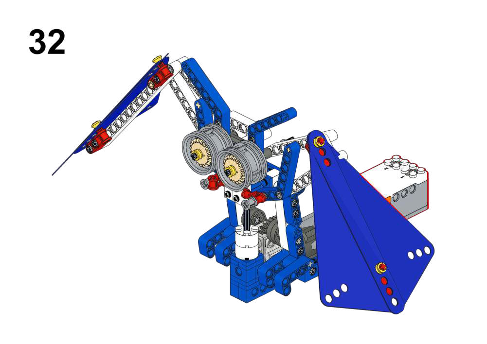
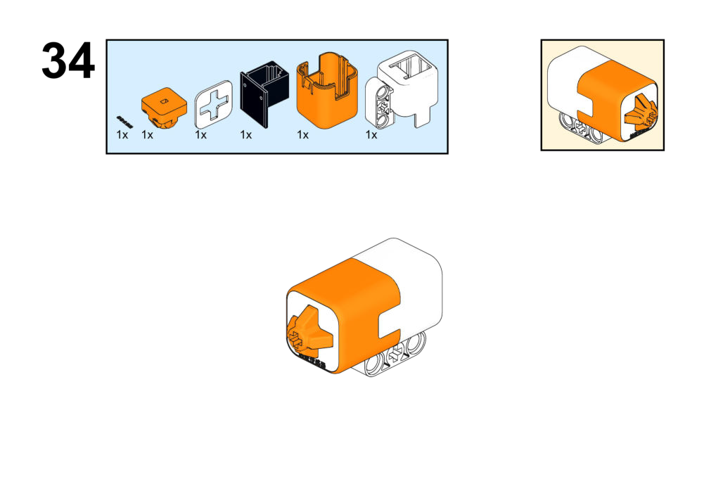
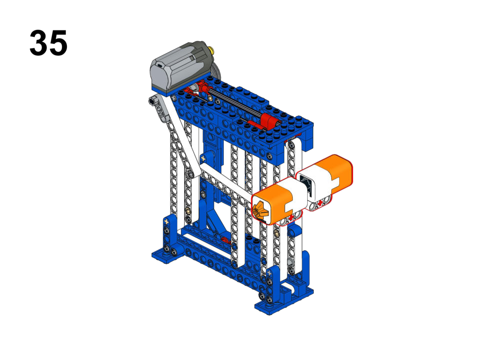
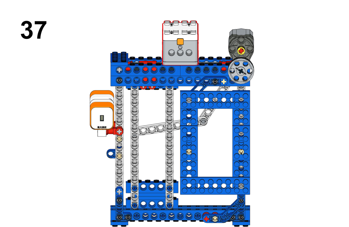
Automatically thrust the sword arm when an opponent is detected within range.View Assembly Instructions

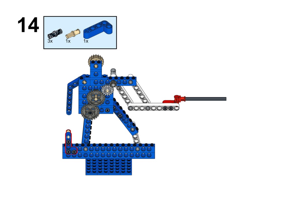
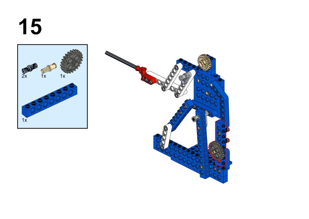
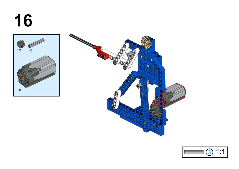
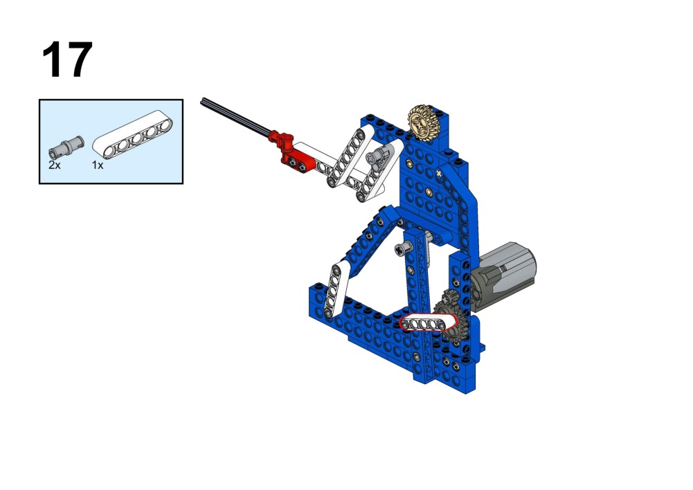
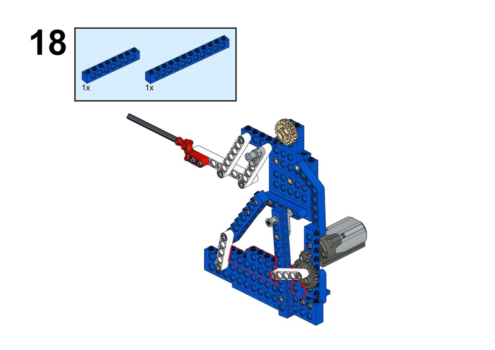
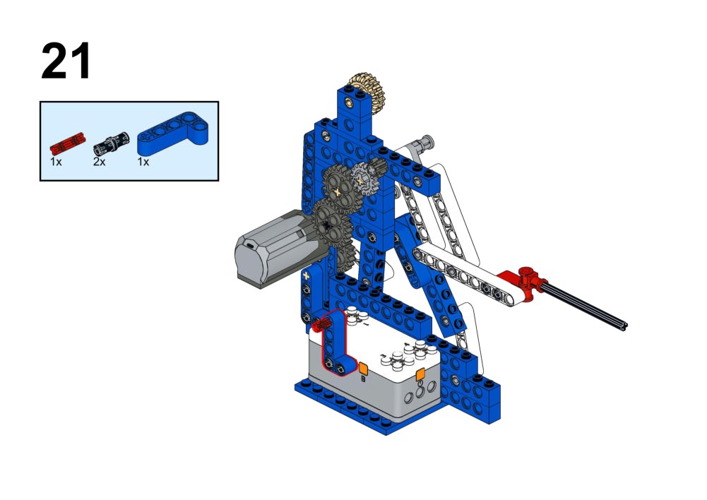
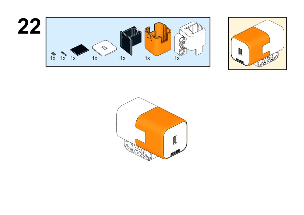
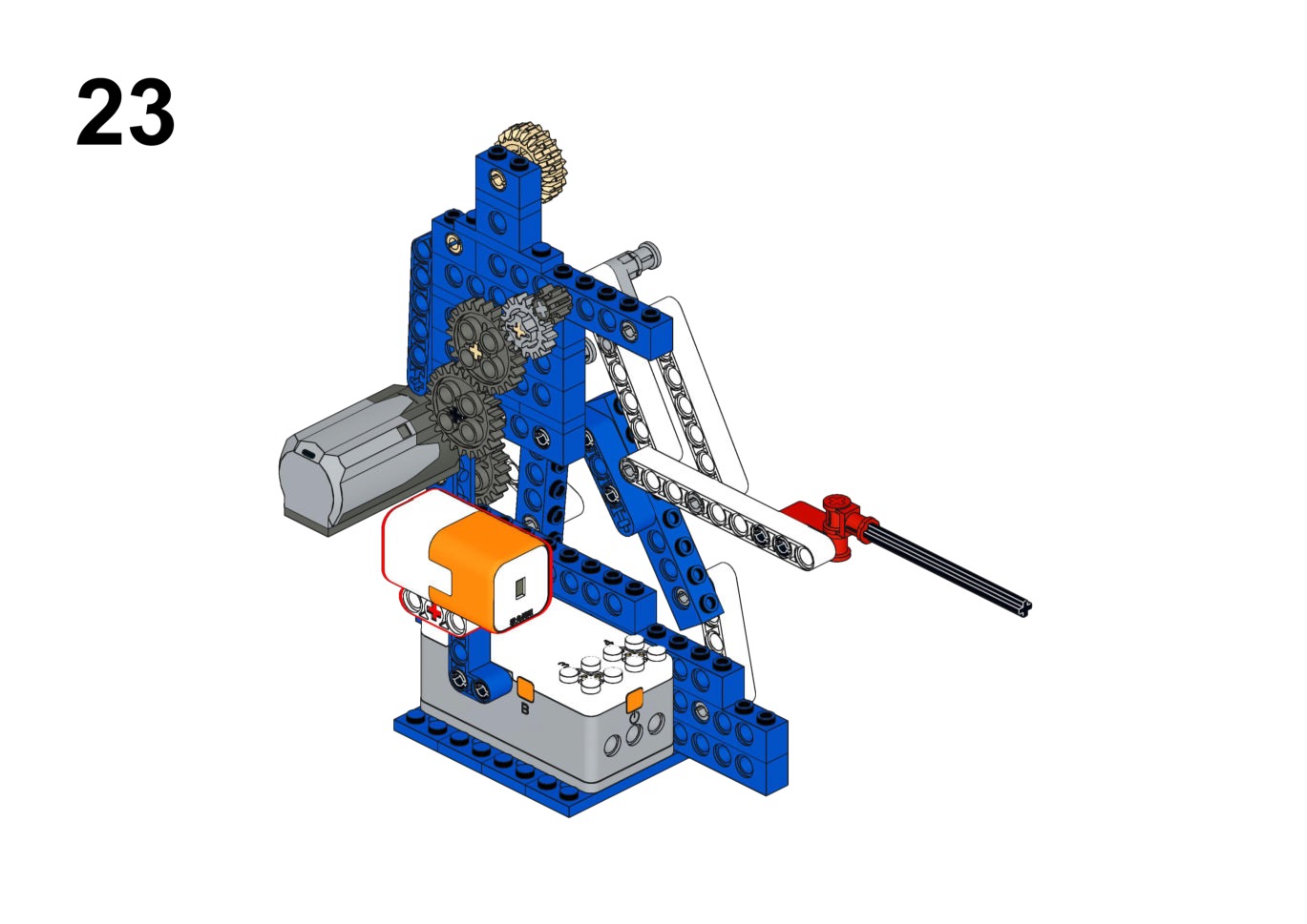
Hardware & Wiring
- Laser Module: Port 4 (Fixed)
- Motor (Arm): Port 1
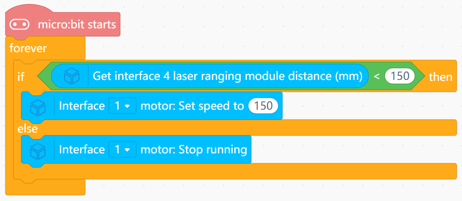
What You Do in Mind+
- Read distance into variable
Dist. - IF
Dist < 150mm: Run motor forward (Thrust). - ELSE: Stop or retract.
View Completed Code
Goal
Start/stop jumping with buttons. Show a smiley face on the LED matrix only when the robot is successfully "jumping".
View Assembly Instructions
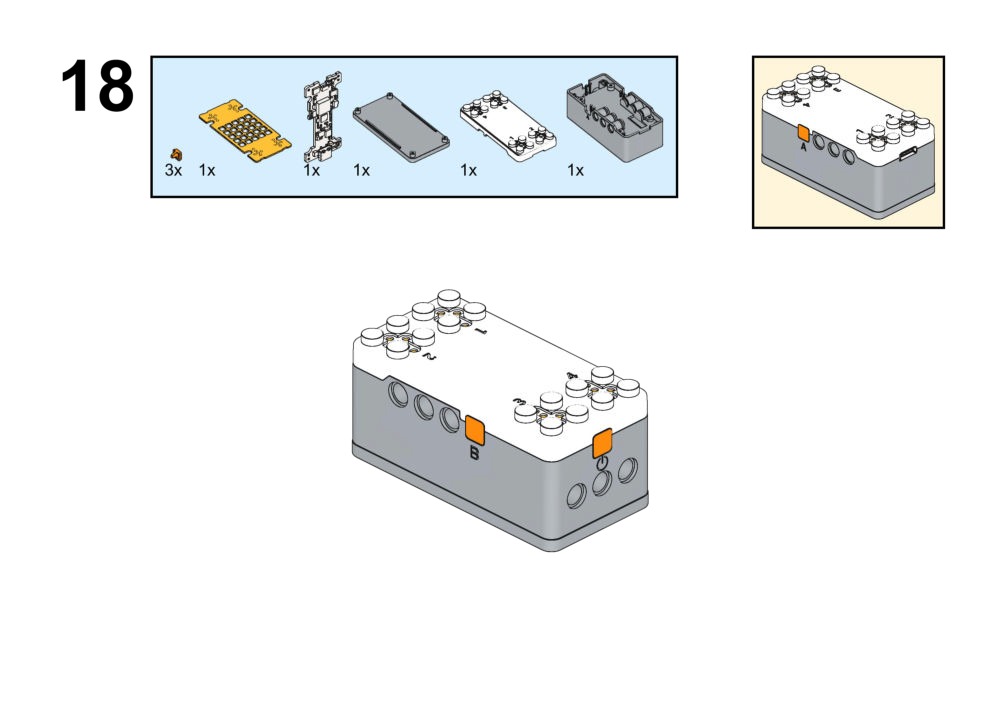
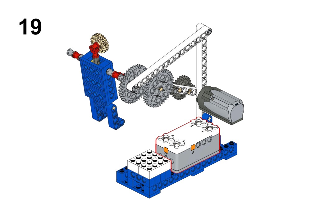
Hardware & Wiring
- Motor: Port 1
- IR Obstacle: Port 3
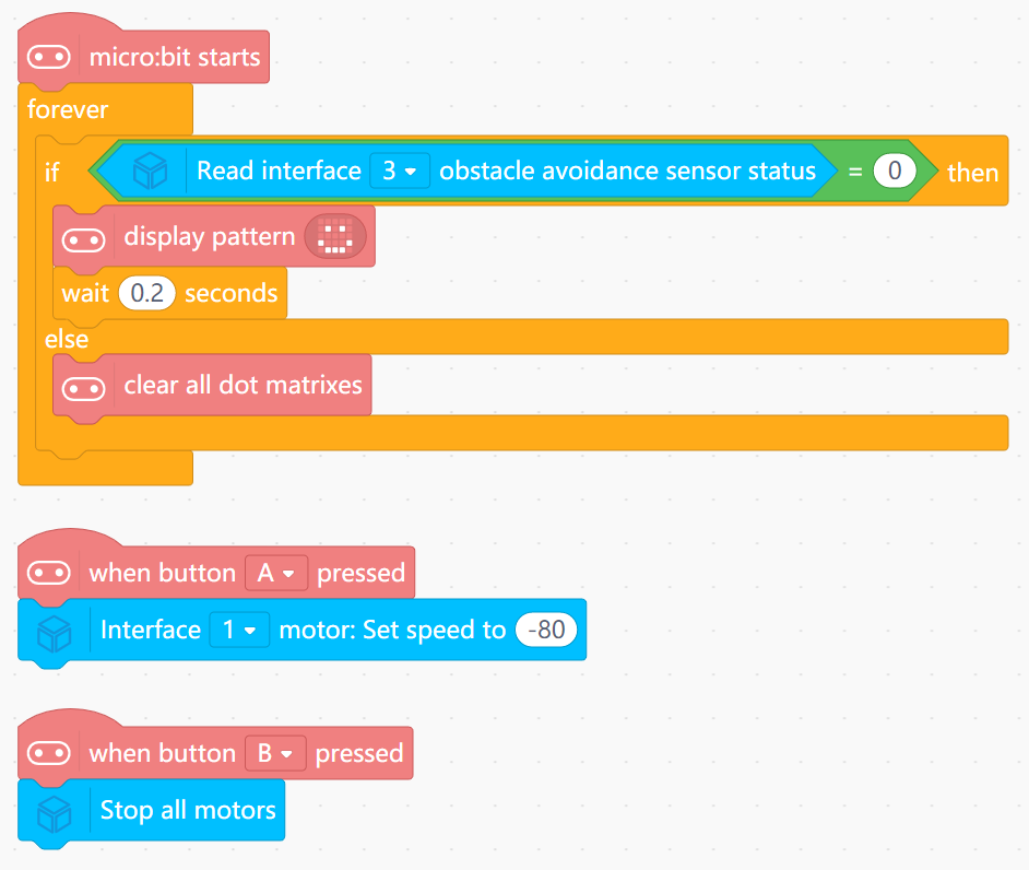
What You Do in Mind+
- Button A: Start Motor. Button B: Stop.
- IF IR sensor detects rope/floor: Show smiley face.
- ELSE: Clear screen.
View Completed Code
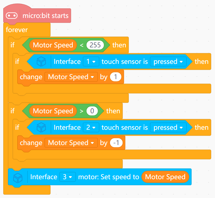
Goal
Let two touch sensors act as "speed-up" and "slow-down" controls for the running robot.
View Assembly Instructions
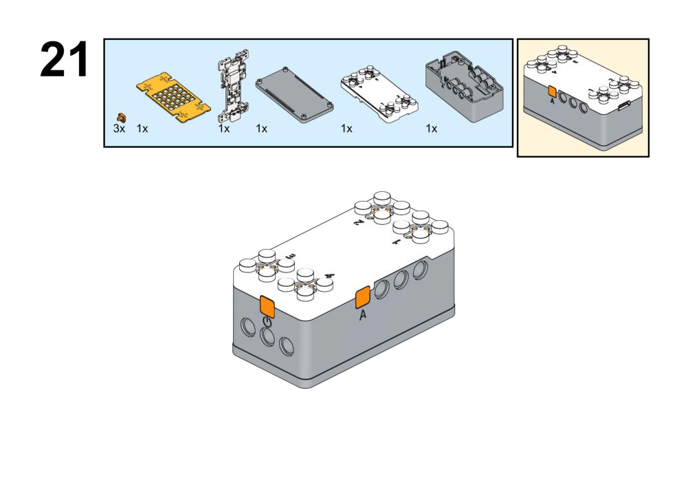
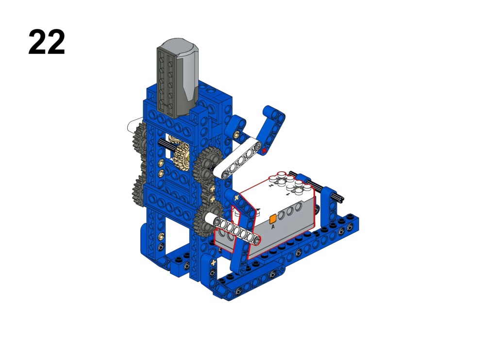
Hardware & Wiring
- Touch 1 & 2: Port 1 & 2
- Motor: Port 3
What You Do in Mind+
- Variable
Speed. - Touch 1 pressed:
Change Speed by +10. - Touch 2 pressed:
Change Speed by -10.
View Completed Code
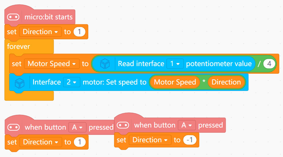
Goal
Control swimming speed by potentiometer and direction by buttons.
View Assembly Instructions
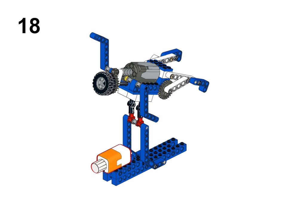
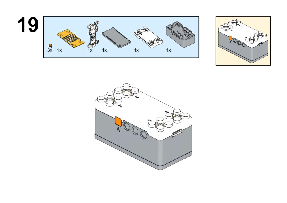
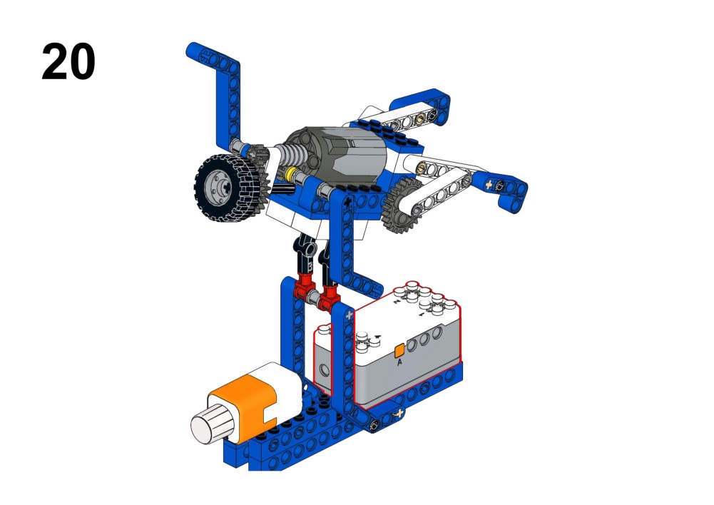
Hardware & Wiring
- Motor: Port 1
- Potentiometer: Port 2
What You Do in Mind+
- Variable
Dir(1 or -1) via Buttons A/B. BaseSpeed = Potentiometer / 4.FinalSpeed = BaseSpeed * Dir.
View Completed Code
Goal
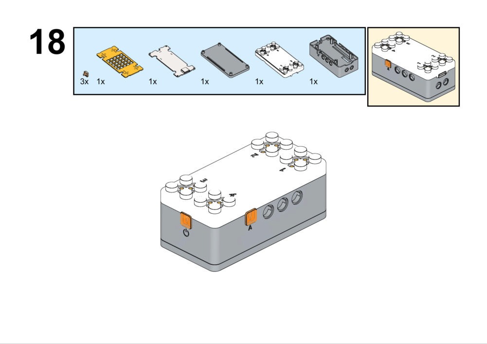
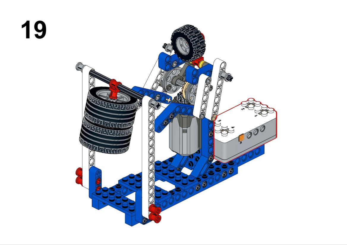
Run a 10-second punching routine, then automatically stop with an audio signal.
View Assembly Instructions
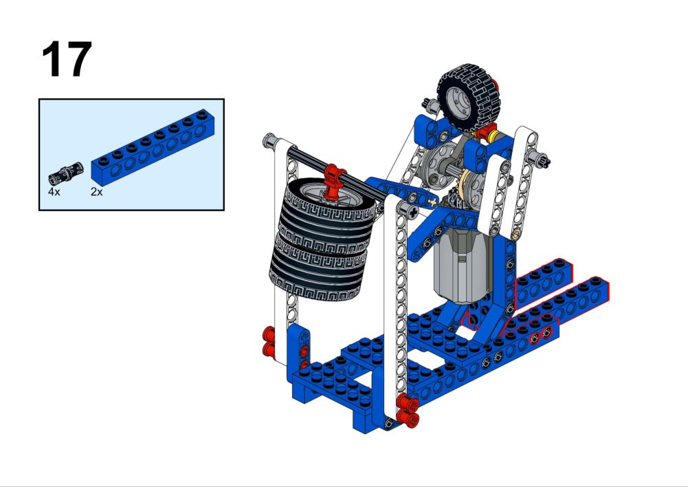
Hardware & Wiring
- Motor: Port 1
- Buzzer: Built-in
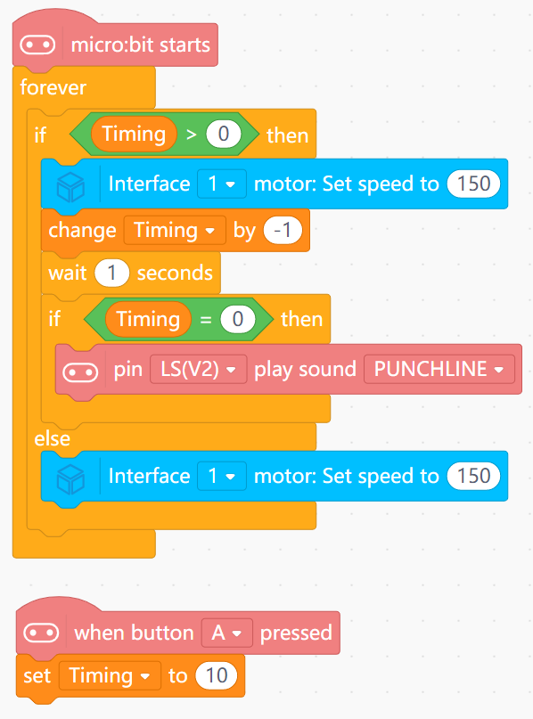
What You Do in Mind+
- Set
Countdown = 10. - Loop while
Countdown > 0:- Run motor, wait 1s, decrease Countdown.
- End: Stop motor, play "Ding" sound.
View Completed Code
Goal
Change robot walking direction according to the controller's orientation.
View Assembly Instructions
Hardware & Wiring
- Accelerometer: Built-in
- Motor: Port 1
What You Do in Mind+
- IF Board Tilted Forward: Motor Forward.
- IF Board Tilted Backward: Motor Reverse.
- Show Arrow icons on Matrix to match direction.
View Completed Code
2. Animals Series (Bio-Inspired)
Focus: Robots that mimic animal behaviors using sensors to react to the environment.
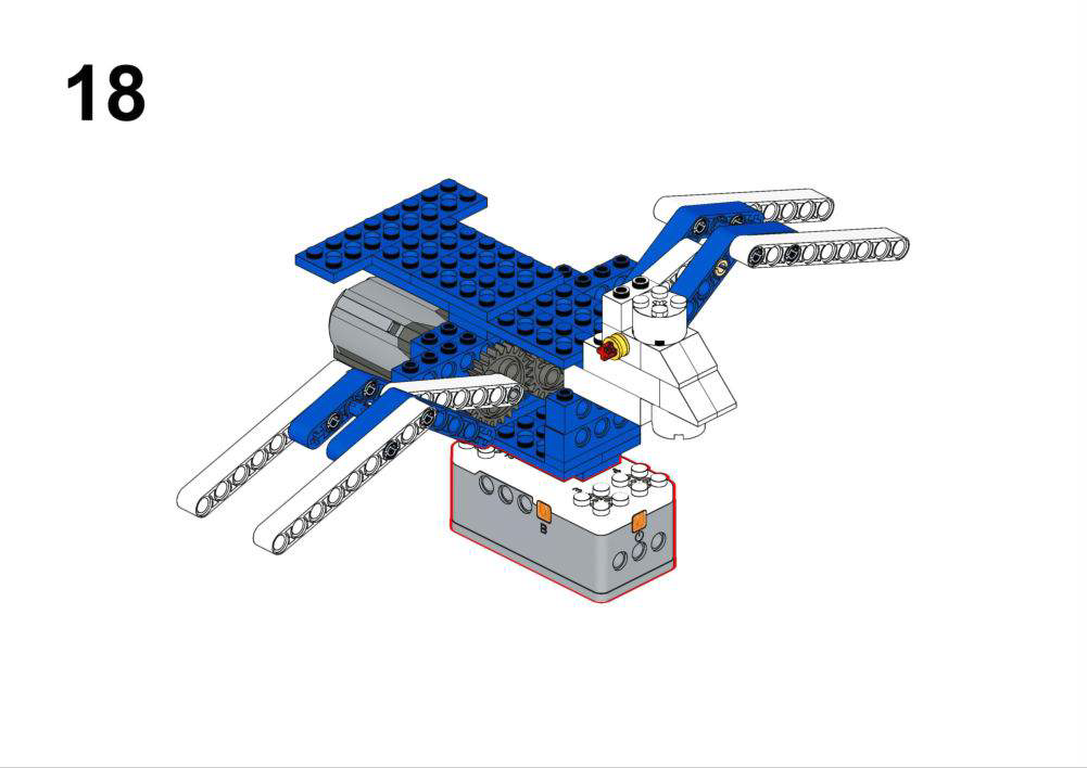
Goal
- Make the bird flap its wings only when being moved.
- Use motion strength to decide flapping speed.
View Assembly Instructions
Hardware & Wiring
- Motor: Port 1
- Accelerometer: Built-in
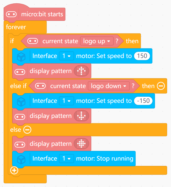
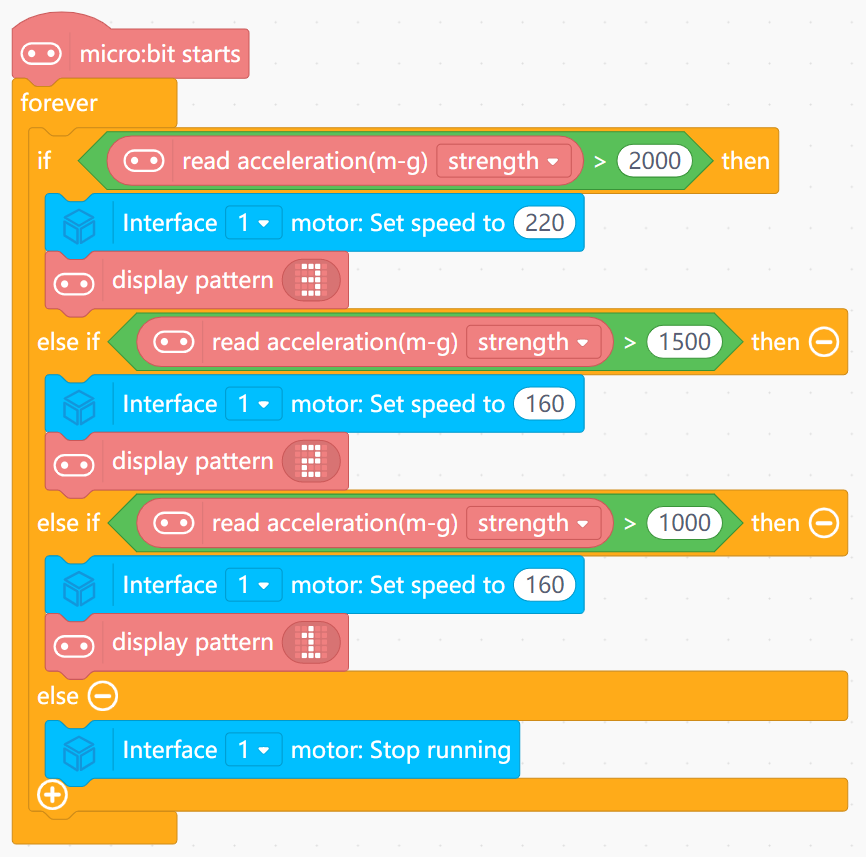
What You Do in Mind+
- In forever:
- Read accelerometer strength block into
Accel. - If
Accel > 1000, set motor speed based on ranges, e.g.:- 1000–1500 → speed 120
- 1500–2000 → speed 160
- >2000 → speed 220
- Else: Tell the motor to stop running.
- Read accelerometer strength block into
View Completed Program
- Uses the accelerometer as a “how strongly you shake” meter.
- Turns this numeric strength into a small set of speed levels.
- Shows that motion can be used as an input, just like light or sound.
Goal
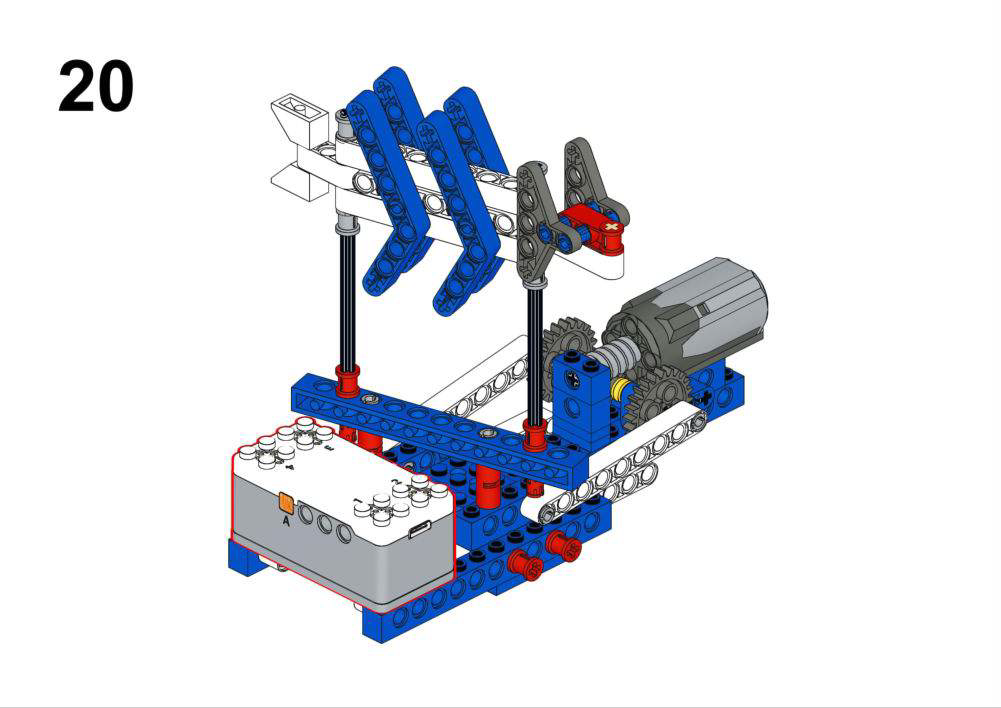
- Make a fish that swims faster in strong light and slower in dim light.
- Demonstrate how to calibrate and use light sensor values.
View Assembly Instructions
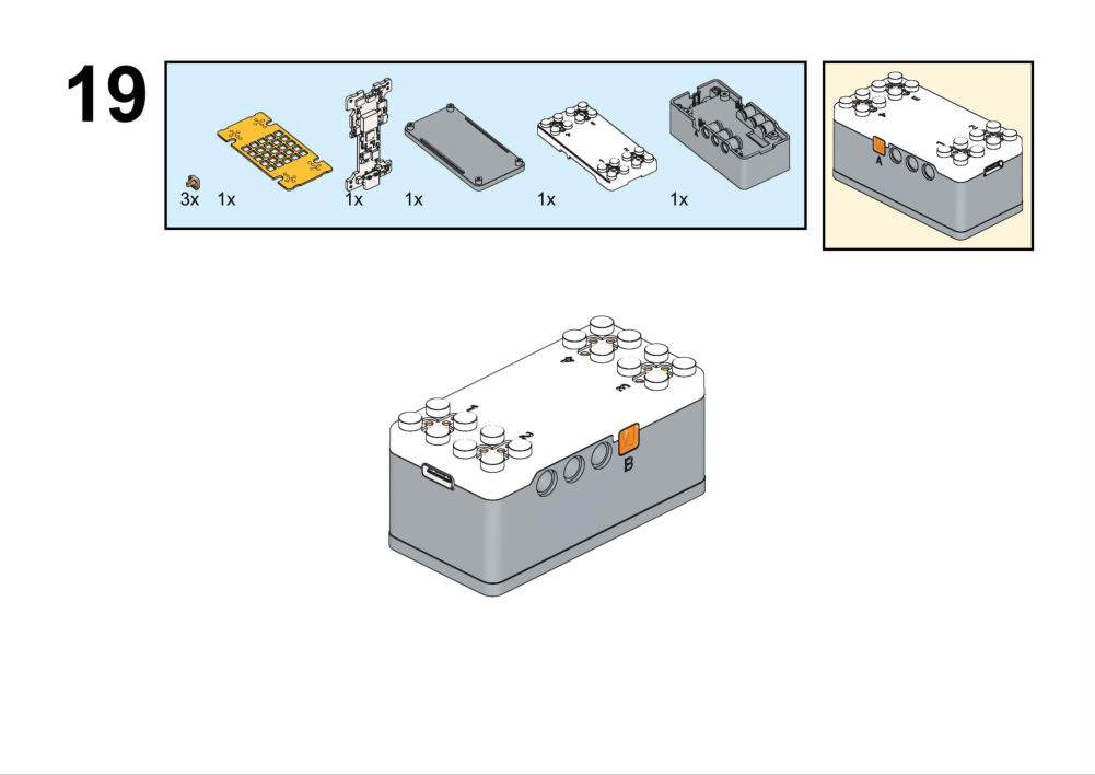
Hardware & Wiring
- Light Sensor: Port 1
- Motor: Port 2
What You Do in Mind+
- Upload a test program:
- In forever, read Light Sensor (Port 1) into
LightValueand print to serial. - Observe typical values in dark vs bright conditions.
- In forever, read Light Sensor (Port 1) into
- Main program:
- In forever, read
LightValue. - If
LightValue > 300, set motor speed based on range, e.g.:- 300–500 → speed 100
- 500–800 → speed 150
- >800 → speed 200
- Else set the motor speed to 0.
- In forever, read
View Completed Program
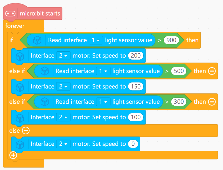
- Shows how to inspect raw sensor values and then define a meaningful range.
- Illustrates both simple threshold behavior and proportional control.
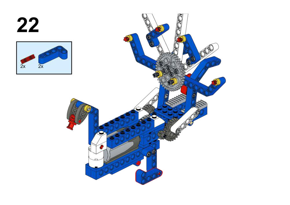
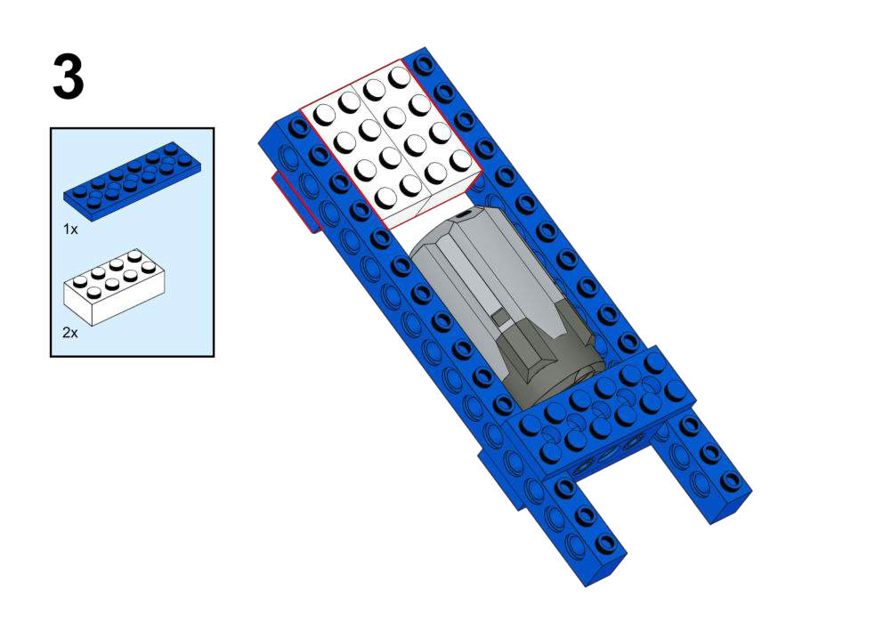
Goal
- Open the peacock’s tail only when it faces a specific direction.
- Use compass degrees with a tolerance range.
View Assembly Instructions
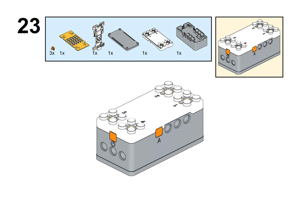
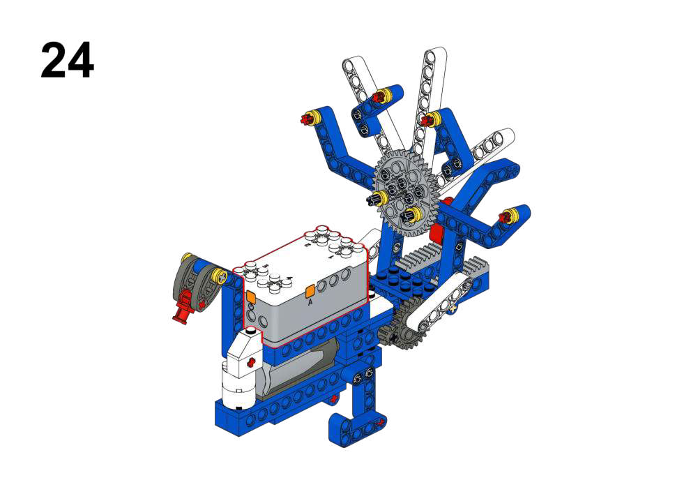


Hardware & Wiring
- Motor: Port 1
- Compass: Built-in
What You Do in Mind+
- Create variable
Heading. - Test program:
- Read compass heading into
Degreeand print via serial while rotating the board.
- Read compass heading into
- Main program:
- In forever, read
Degree. - If
Degree ≥ 80ANDDegree ≤ 100:- Run Motor (Port 1) at speed 150 (tail open).
- Else:
- Stop motor (tail closed).
- In forever, read
View Completed Program
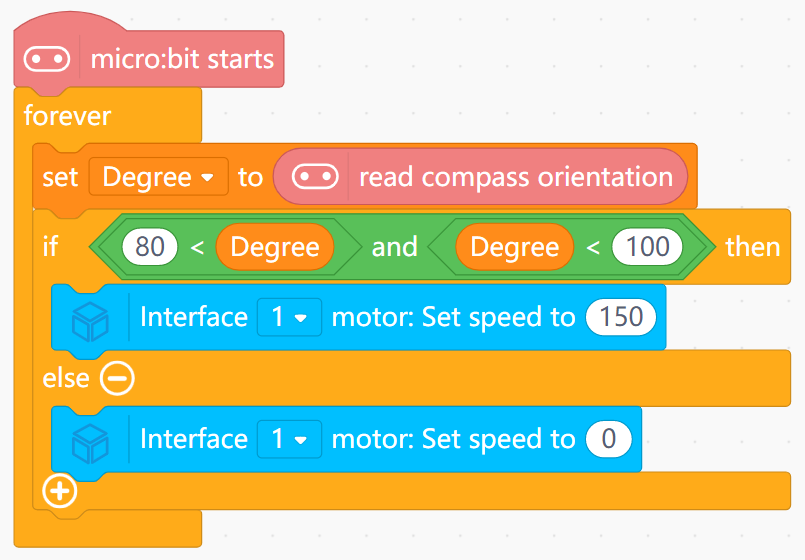
- Turns continuous compass data into a discrete “direction window”.
- Shows why ranges are used instead of a single degree value.
Goal
- Let the kangaroo run away when a loud noise (danger) is detected.
- Use the LED matrix to show a heartbeat animation during escape.
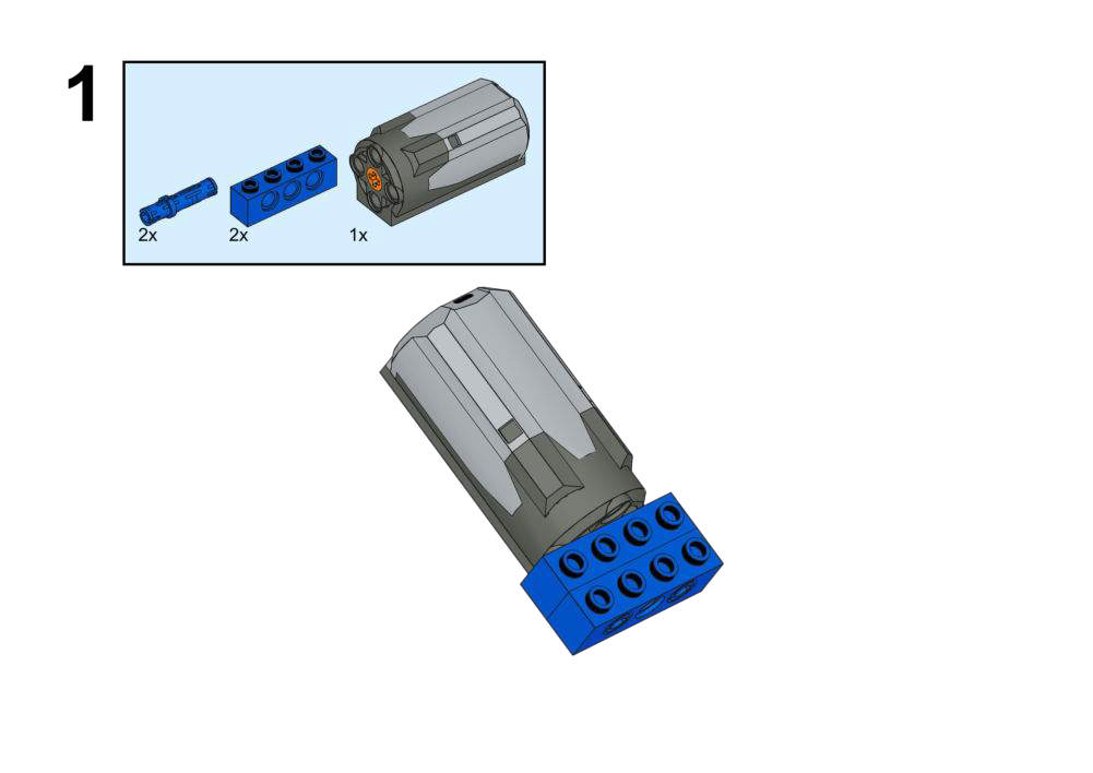
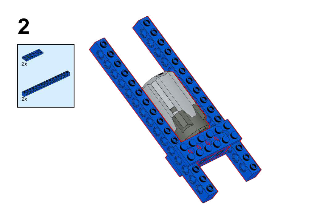
View Assembly Instructions
Hardware & Wiring
- Sound Sensor: Port 1
- Motor: Port 2
What You Do in Mind+
- Test program:
- Use serial to display sound sensor state (0/1) as you clap or speak.
- Main program:
- In forever, read sound sensor state.
- If
sound state == 1:- Run Motor (Port 2) at escape speed (150).
- Loop through several matrix icons every 0.5 s to simulate heartbeat.
- Else:
- Stop motor and show a calm icon or clear matrix.
View Completed Program
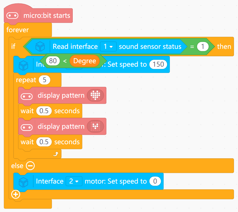
- Transforms a digital “danger present” signal into a combined motion + visual response.
- Reinforces that sensors often represent real-world categories (safe vs dangerous) in a simple 0/1 form.
Goal
Create a rabbit that moves closer to or away from your hand to maintain a comfortable distance.
View Assembly Instructions
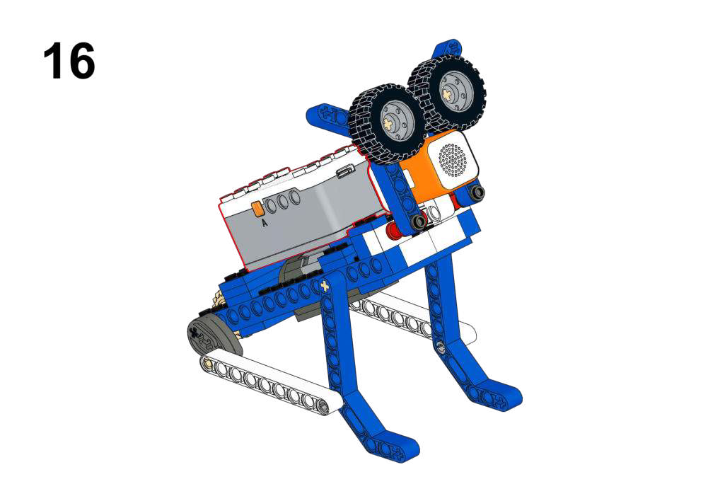
Hardware & Wiring
- Laser Module: Port 4
- Motor: Port 1
What You Do in Mind+
- Create variable
Distance. - In forever:
- Read distance from Laser Range into
Distance. - If
150 ≤ Distance ≤ 300:- Motor (Port 1) forward (follow, speed 150).
- Else if
Distance < 120:- Motor reverse (move away, speed -150).
- Else:
- Motor stop.
- Read distance from Laser Range into
View Completed Program
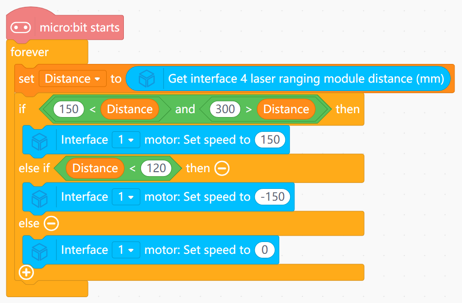
- Uses two distance thresholds to define a “comfort band”.
- Implements a simple feedback behavior: too close → back off; too far → move closer.
Goal
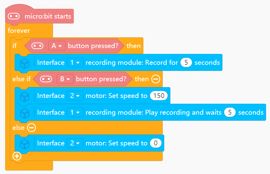
Record a custom “pterosaur cry” and replay it while the wings flap.
View Assembly Instructions

Hardware & Wiring
- Recording Module: Port 1
- Motor: Port 2
What You Do in Mind+
- Use module’s “record” and “play” blocks:
- On Button A pressed:
- Start recording for 5 seconds.
- On Button B pressed:
- Play back for 5 seconds.
- At the same time, run Motor (Port 2) to flap wings (speed 150).
- Else:
- Motor stop.
View Completed Program
- Illustrates asynchronous behavior: record at one time, replay later on demand.
- Ties audio output to a simultaneous mechanical motion.
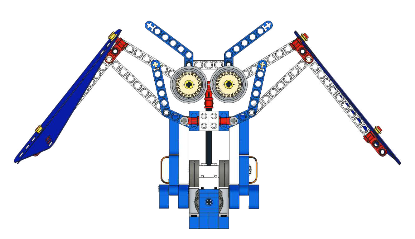
Goal
Make the owl rest when environment is bright and flap + hoot when it is dark.
View Assembly Instructions
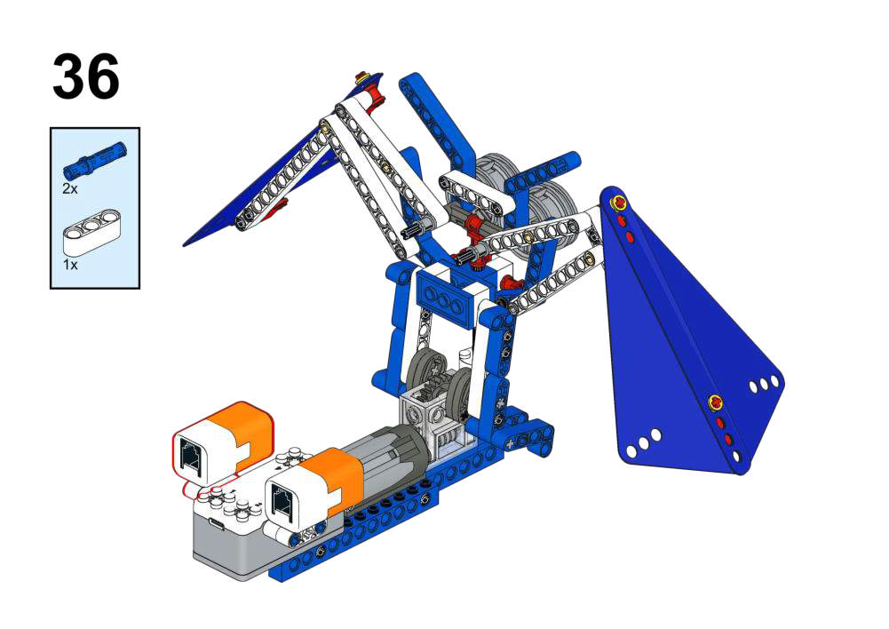
Completed Construction:
Hardware & Wiring
- Light Sensor: Port 1
- Recording: Port 2
- Motor: Port 3
What You Do in Mind+
- Button A:
- Record owl call using recording module for 3 seconds.
- In forever:
- Read Light Sensor value.
- If light sensor value is low (<300, night):
- Run Motor (Port 3) at speed 150.
- Play recorded owl call for 3 seconds.
- If light sensor value is high (daytime):
- Stop Motor; do not play sound.
View Completed Program
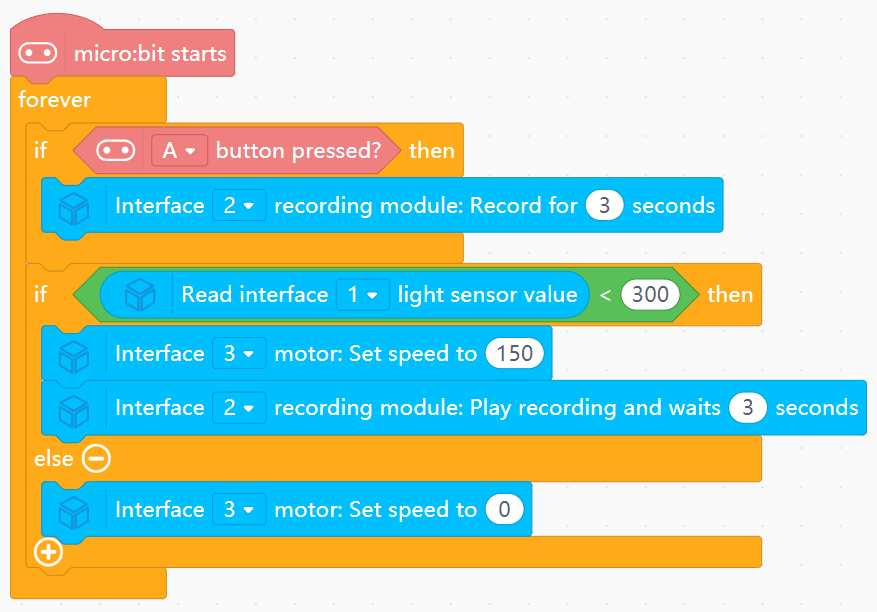
- Implements a simple “night-only” mode based on light threshold.
- Combines environmental sensing with pre-recorded audio cues.
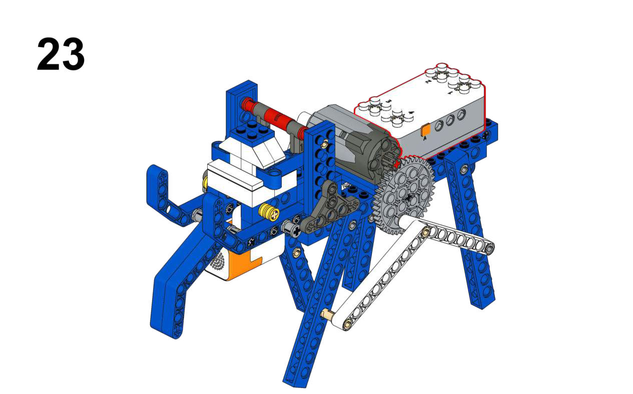
Goal
- Control elephant’s trunk/body motion with voice commands.
- Adjust motor speed via voice-controlled variable.
View Assembly Instructions
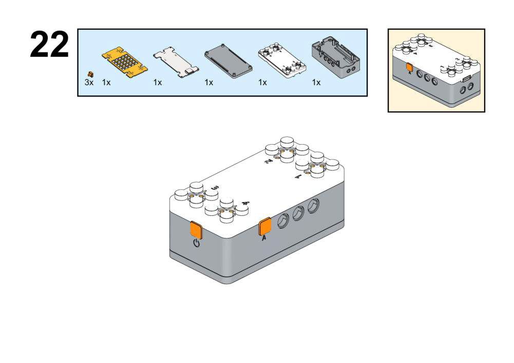
Hardware & Wiring
- Voice Module: Port 1
- Motor: Port 2
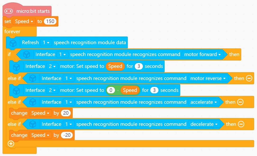
What You Do in Mind+
- Create variable
Speedwith initial value 150. - In forever:
- Refresh voice module data (Port 1).
- Read recognized command index into
Command. - If command = “motor forward”:
- Run motor (Port 2) forward for 3 seconds at current
Speed.
- Run motor (Port 2) forward for 3 seconds at current
- If command = “motor reverse”:
- Run motor backward for 3 seconds at
0 - Speed.
- Run motor backward for 3 seconds at
- If command = “faster” → increase
Speedby 20; “slower” → decrease by 20.
View Completed Program
3. Amusement Park Series (Physics & Rides)
Focus: Simulating ride mechanics using continuous, timed, or event-driven motors.
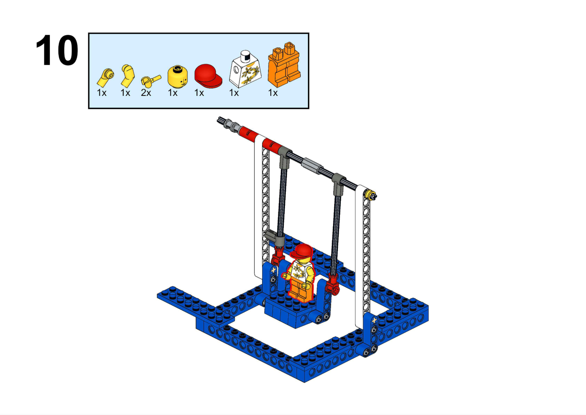
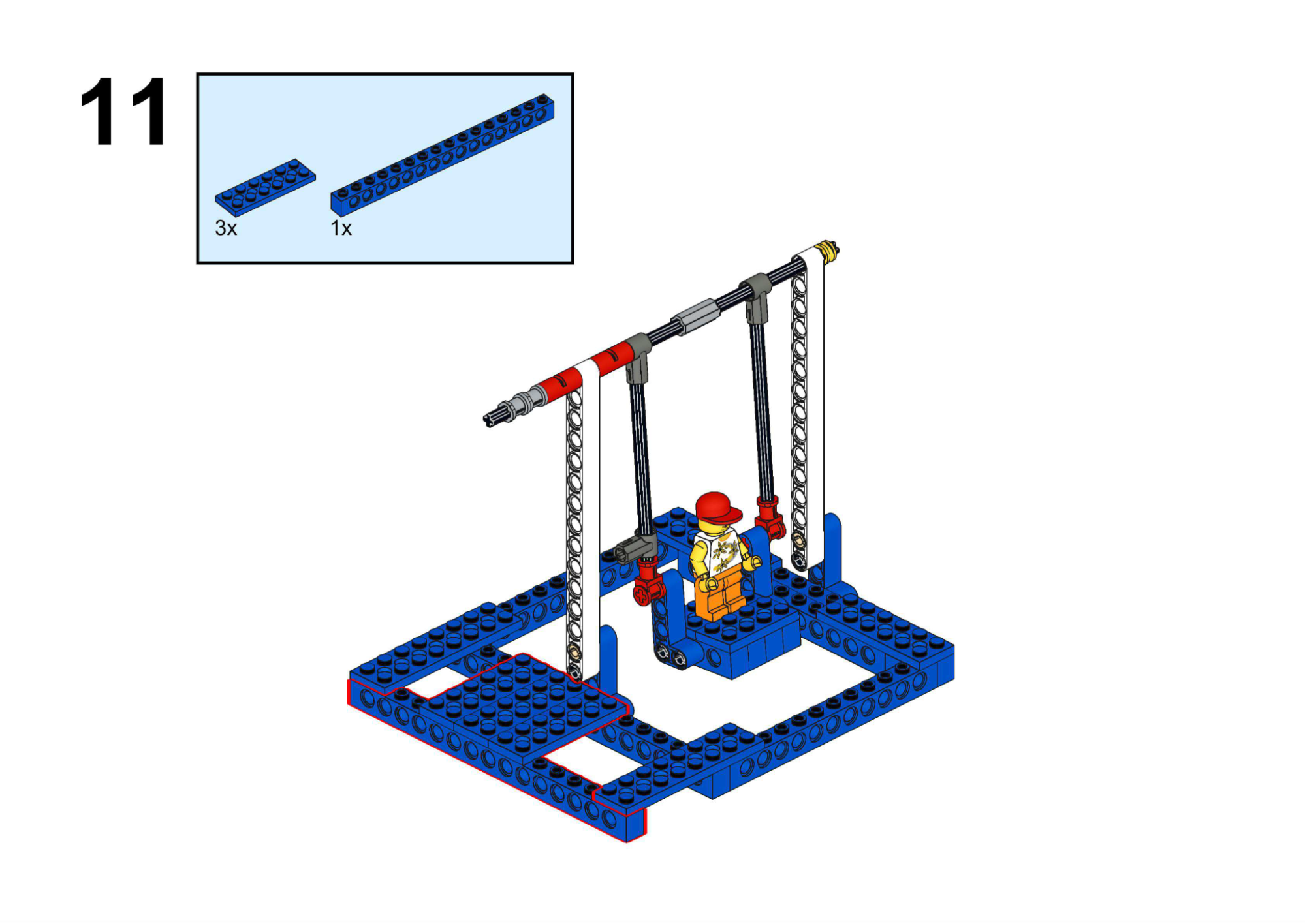
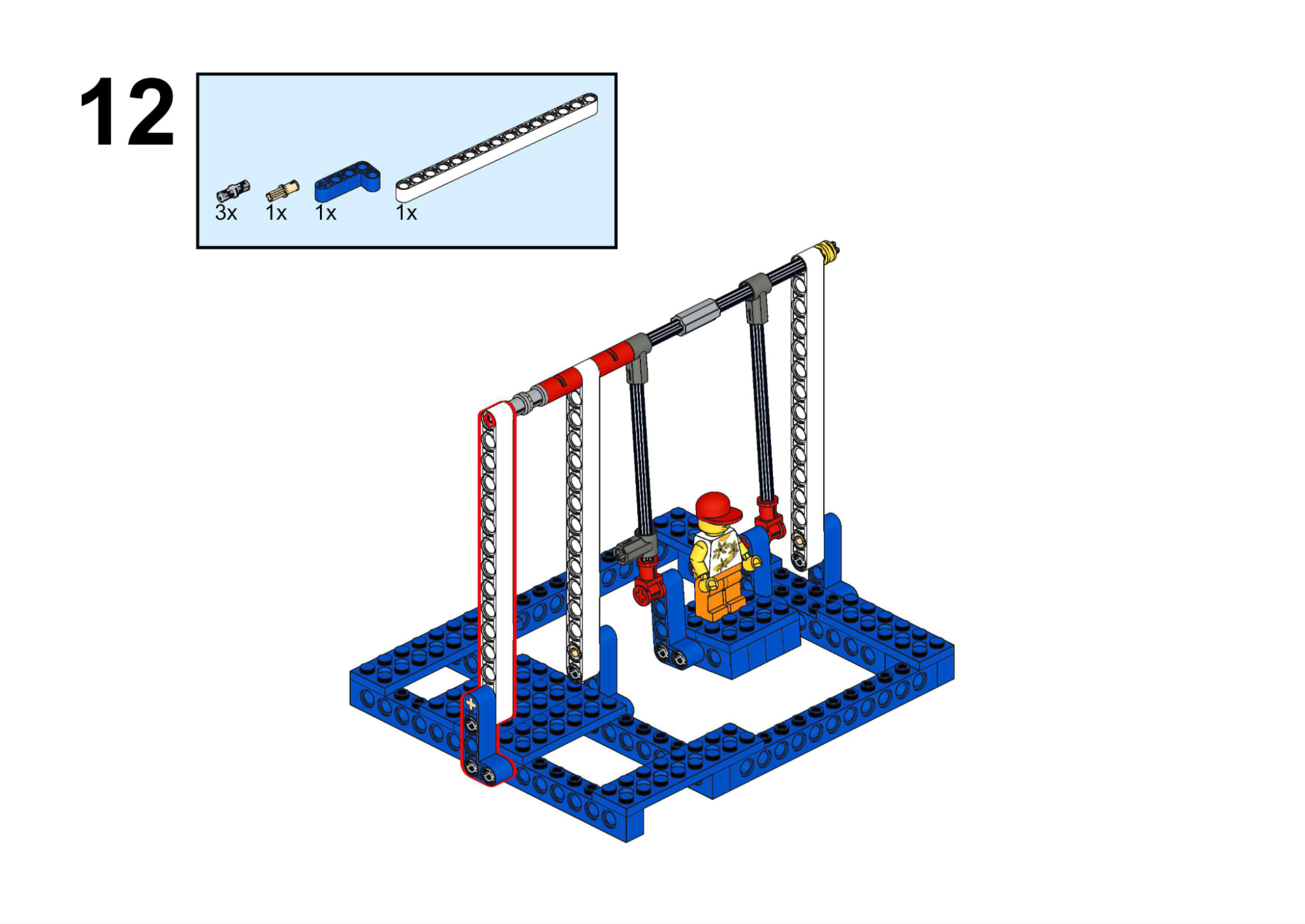
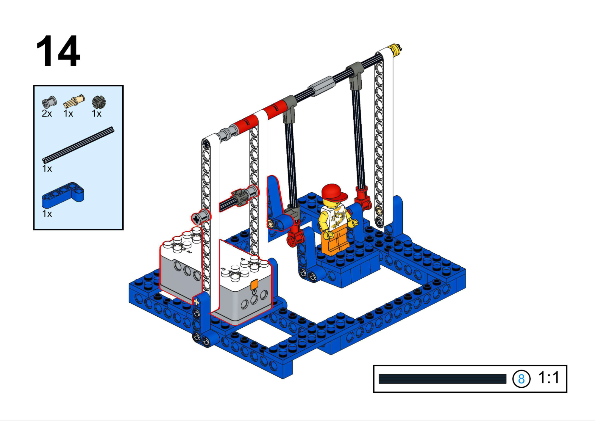
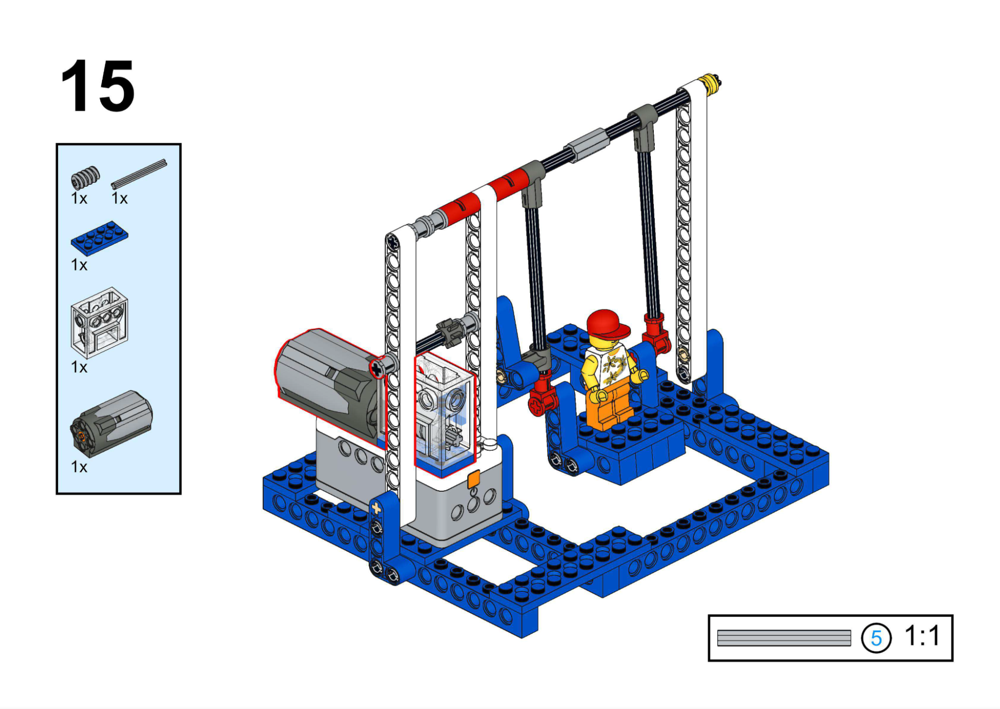
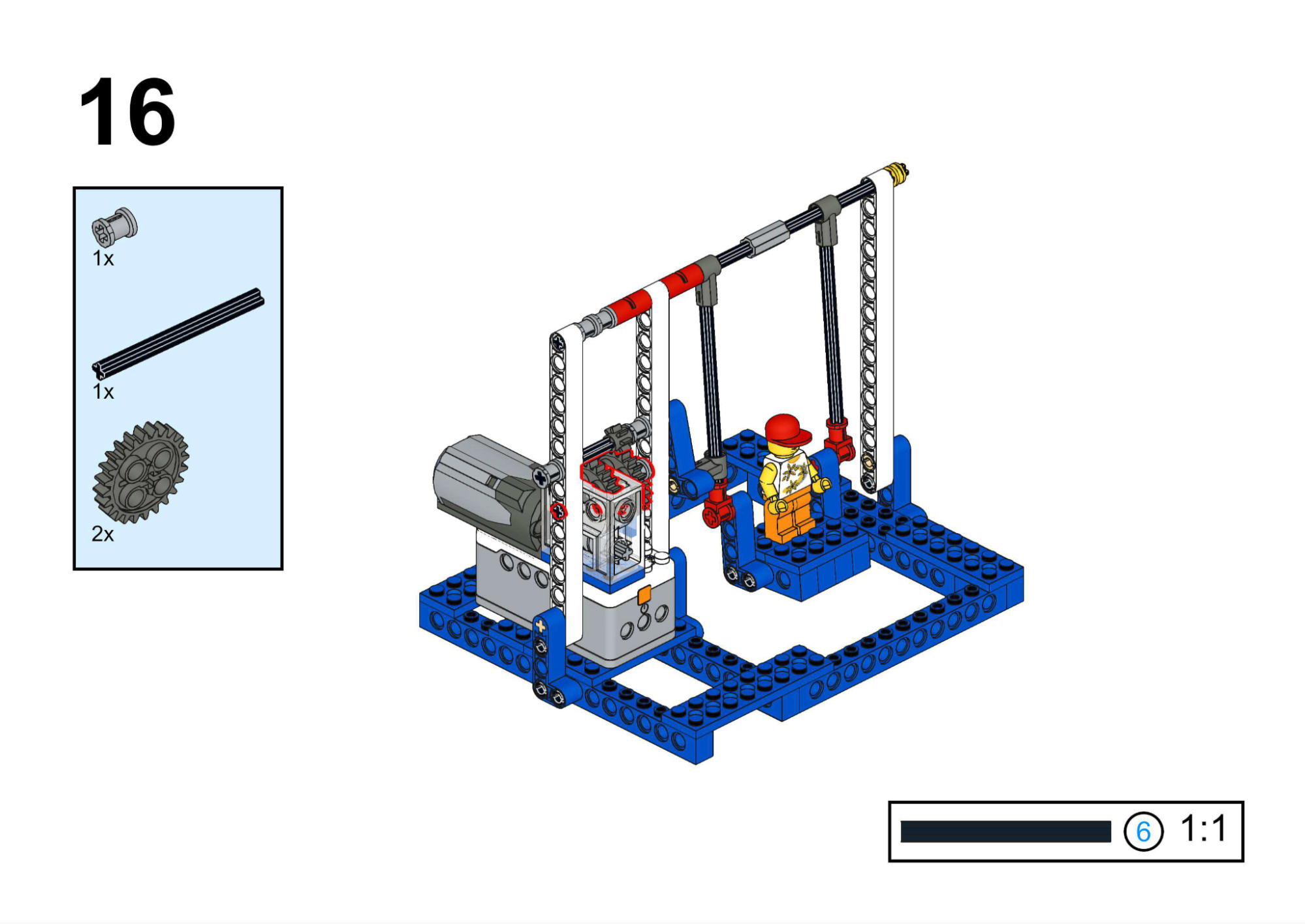
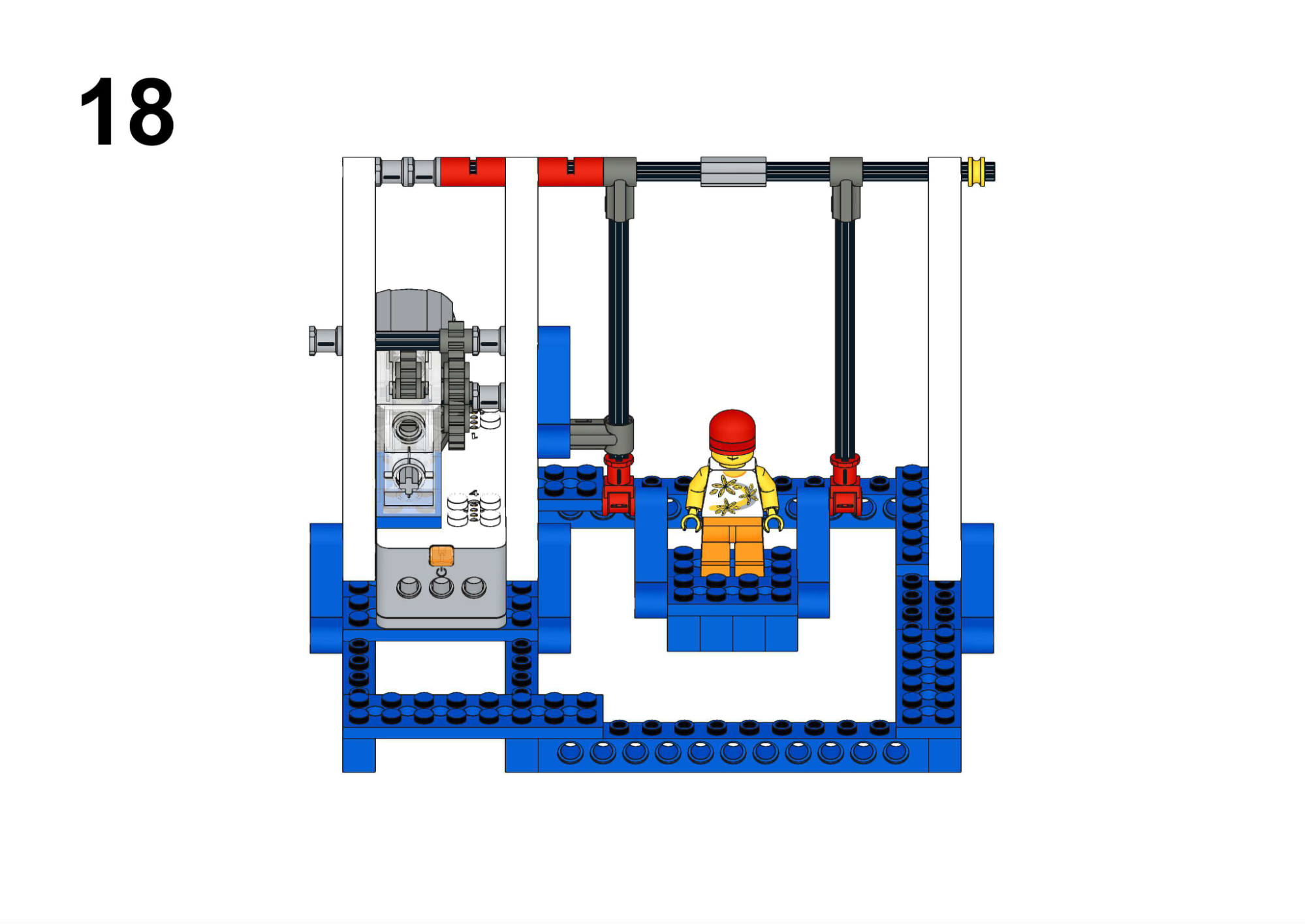
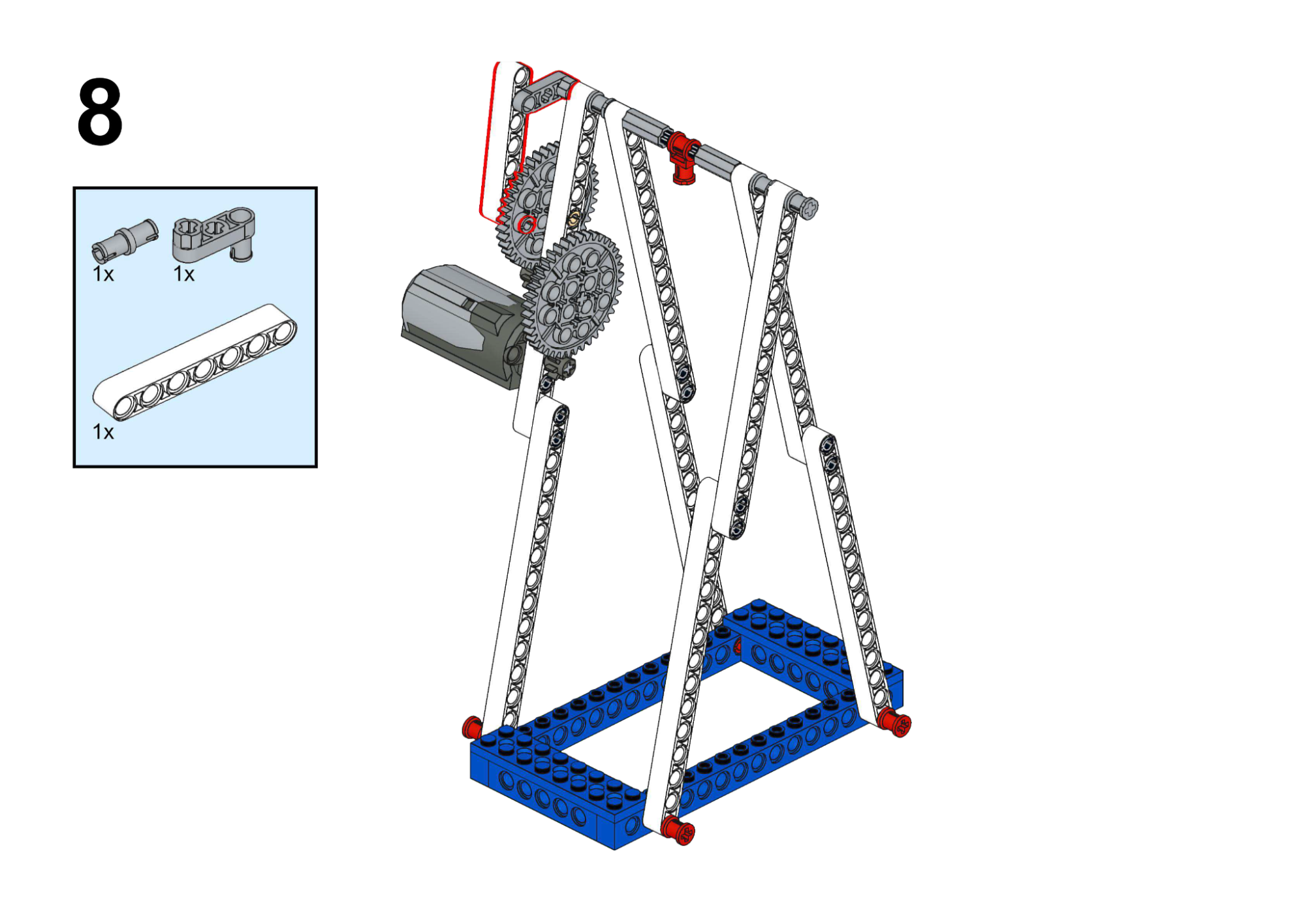
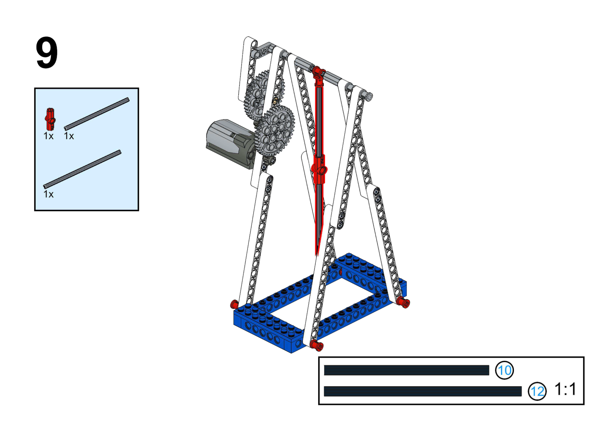
Goal
- Drive the swing back and forth using a continuous motor.
- Introduce basic motor speed control.
View Assembly Instructions
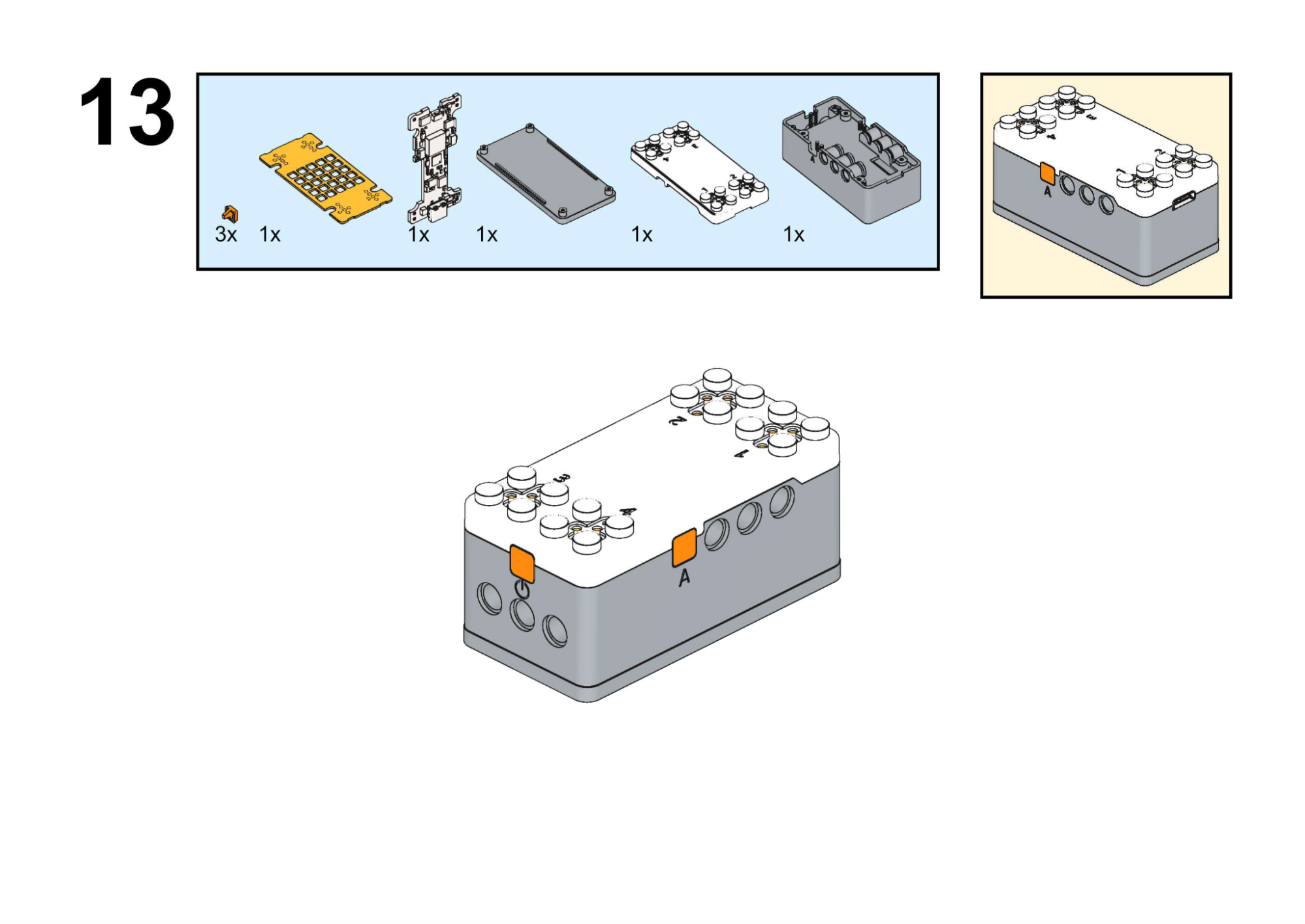
Hardware & Wiring
- Motor: Port 1
Mind+ Logic
- Use the motor speed block:
- In forever, set Motor (Port 1) speed to 255 (maximum forward).
- Upload and observe continuous swinging motion through worm-geared linkage.
View Completed Program
Goal
Play built-in music while the carousel rotates and horses move up/down.
View Assembly Instructions
Hardware & Wiring
- Motor: Port 1
- Buzzer: Built-in
Mind+ Logic
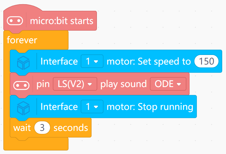
- In a sequence:
- Turn Motor (Port 1) speed to 150.
- Use Music block to play a built-in song (blocking, pin LS(V2)).
- After music ends, set motor speed to 0.
- Wait 3 seconds.
- Optionally edit the song by changing the built-in tune or moving to custom notes.
View Completed Program
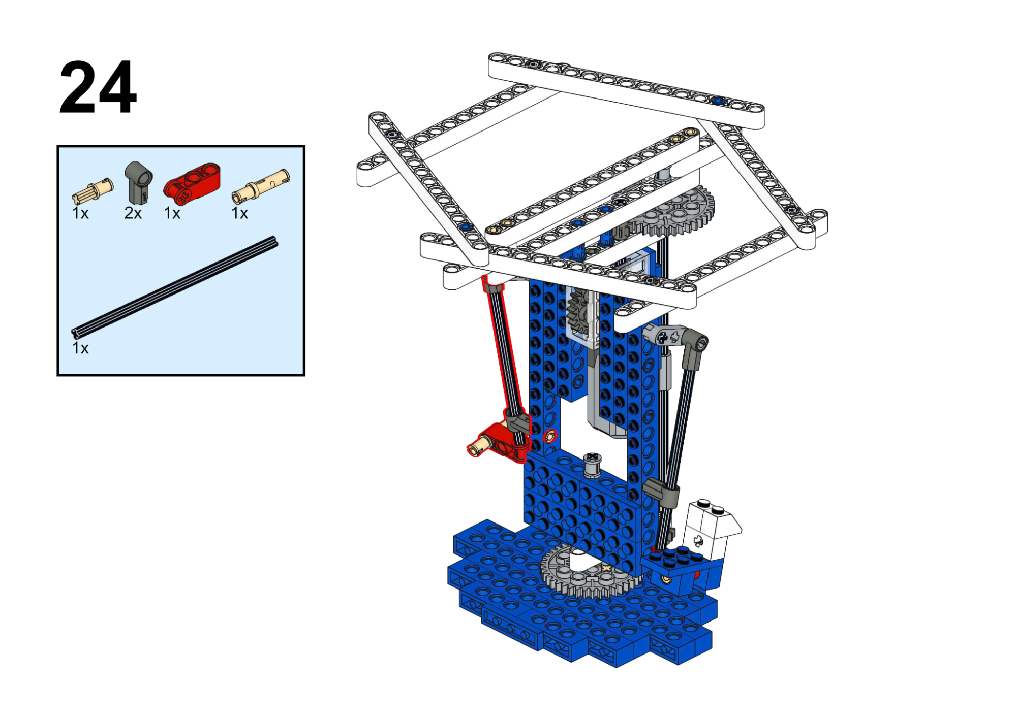
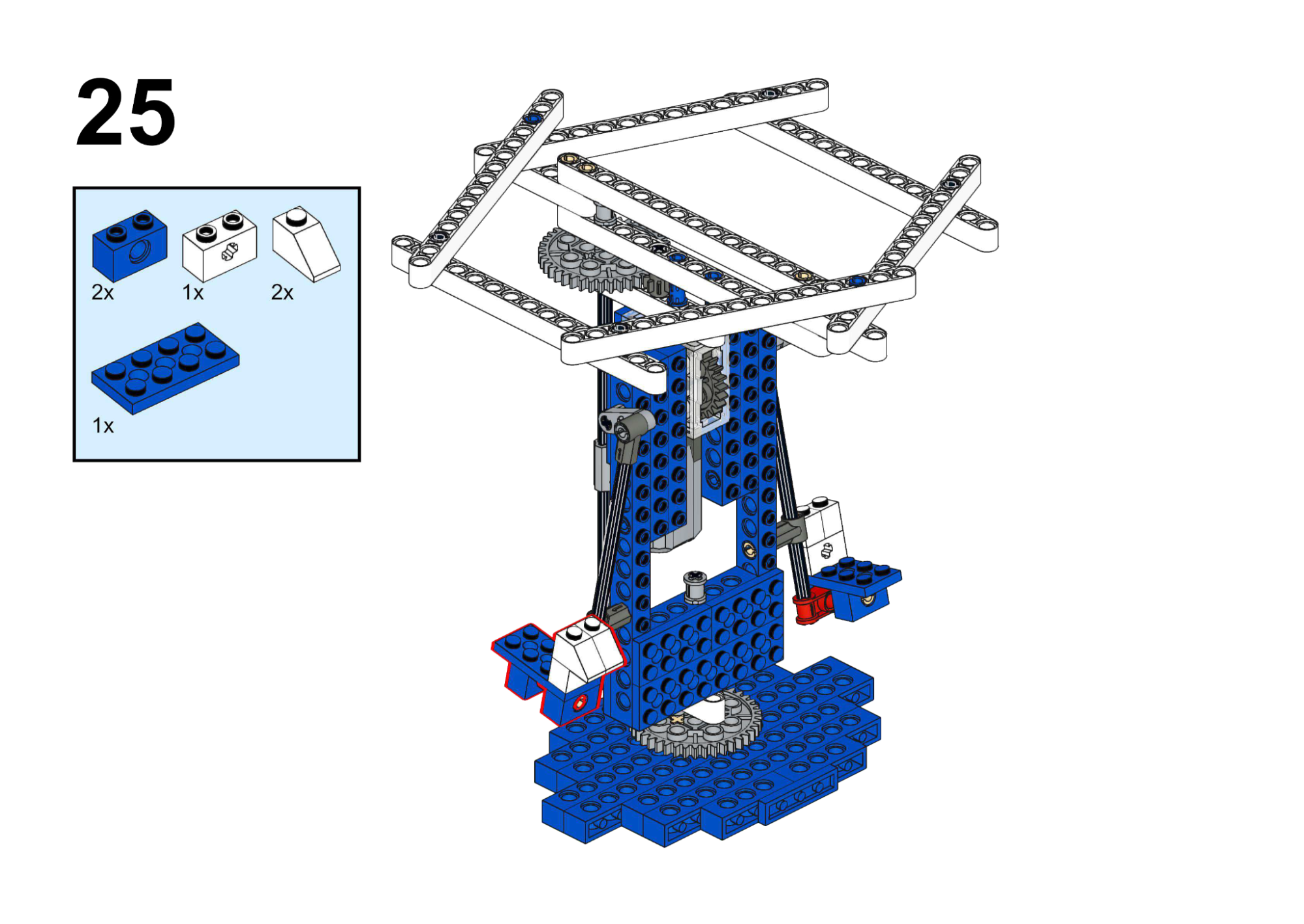
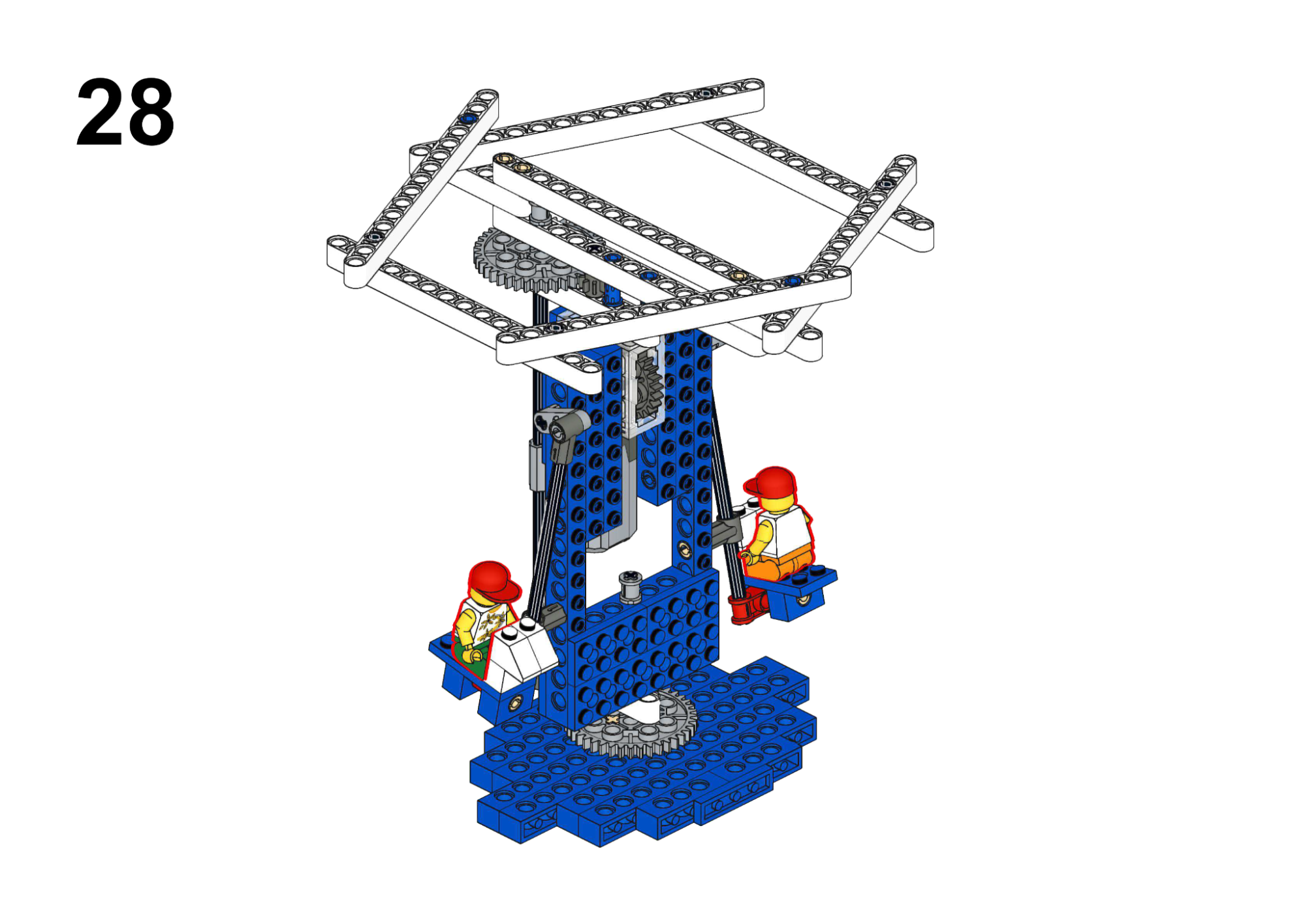
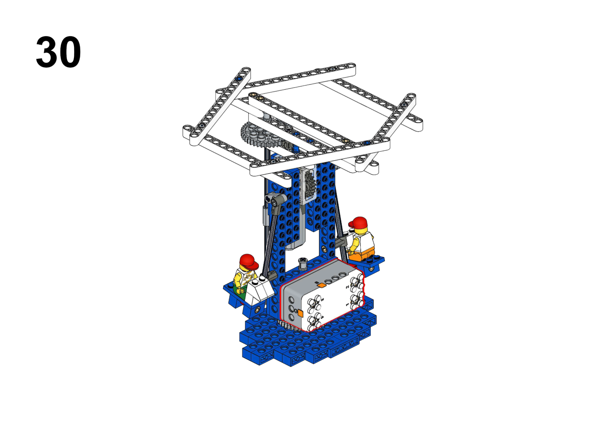
Goal
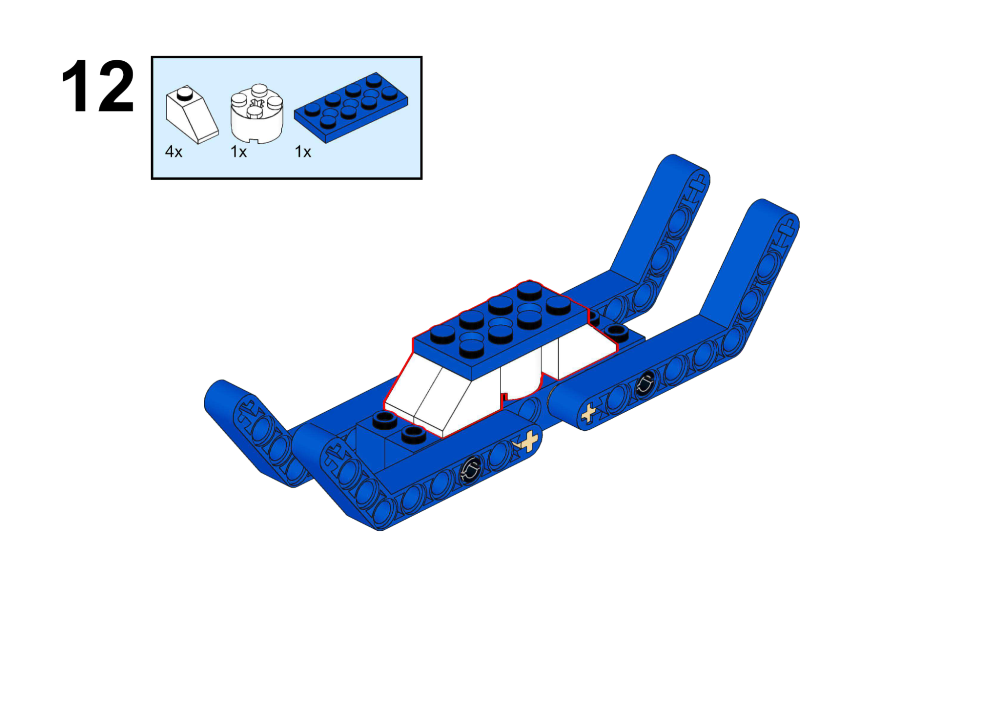
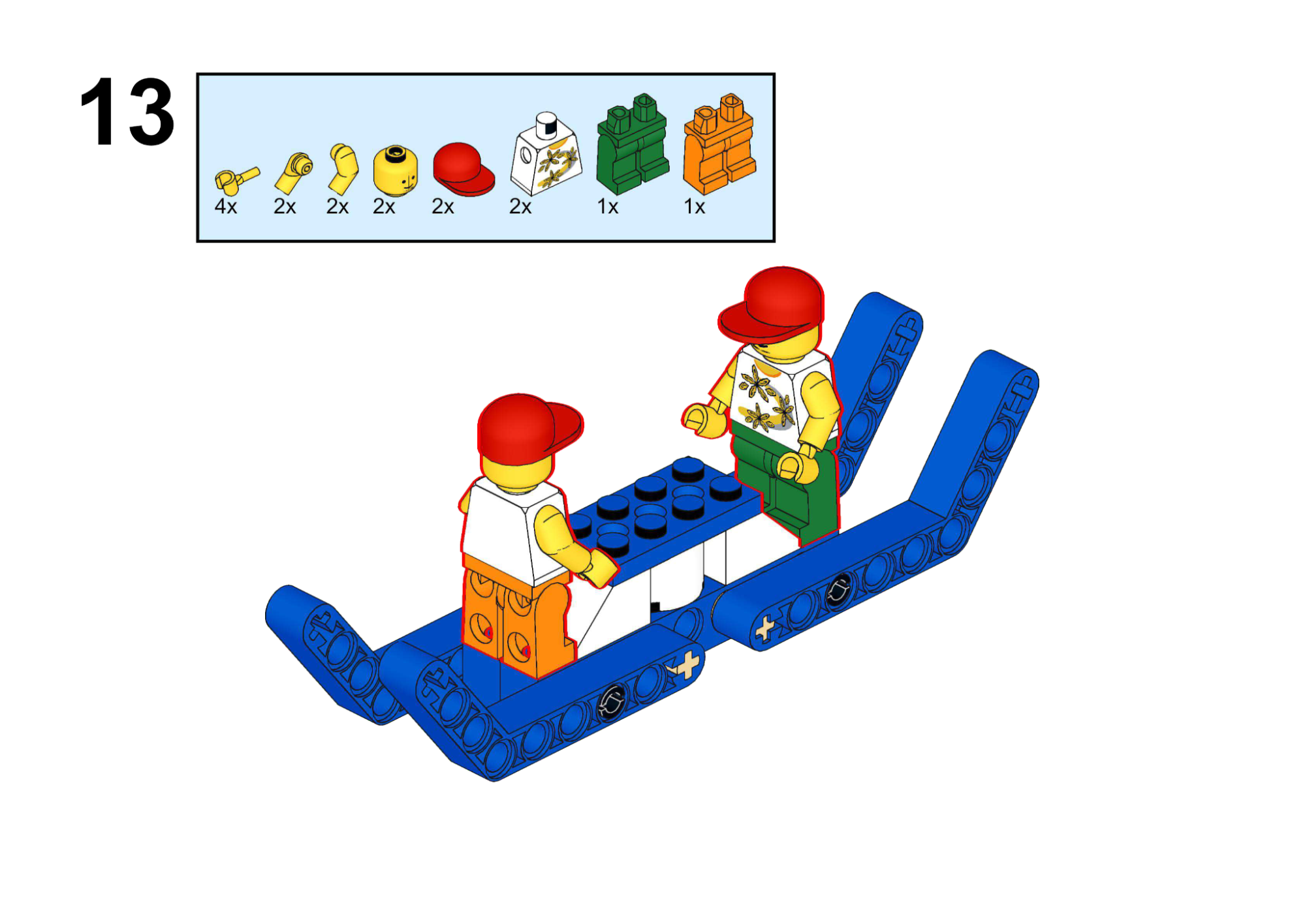
Simulate the ship swinging with increasing speed and amplitude.
View Assembly Instructions
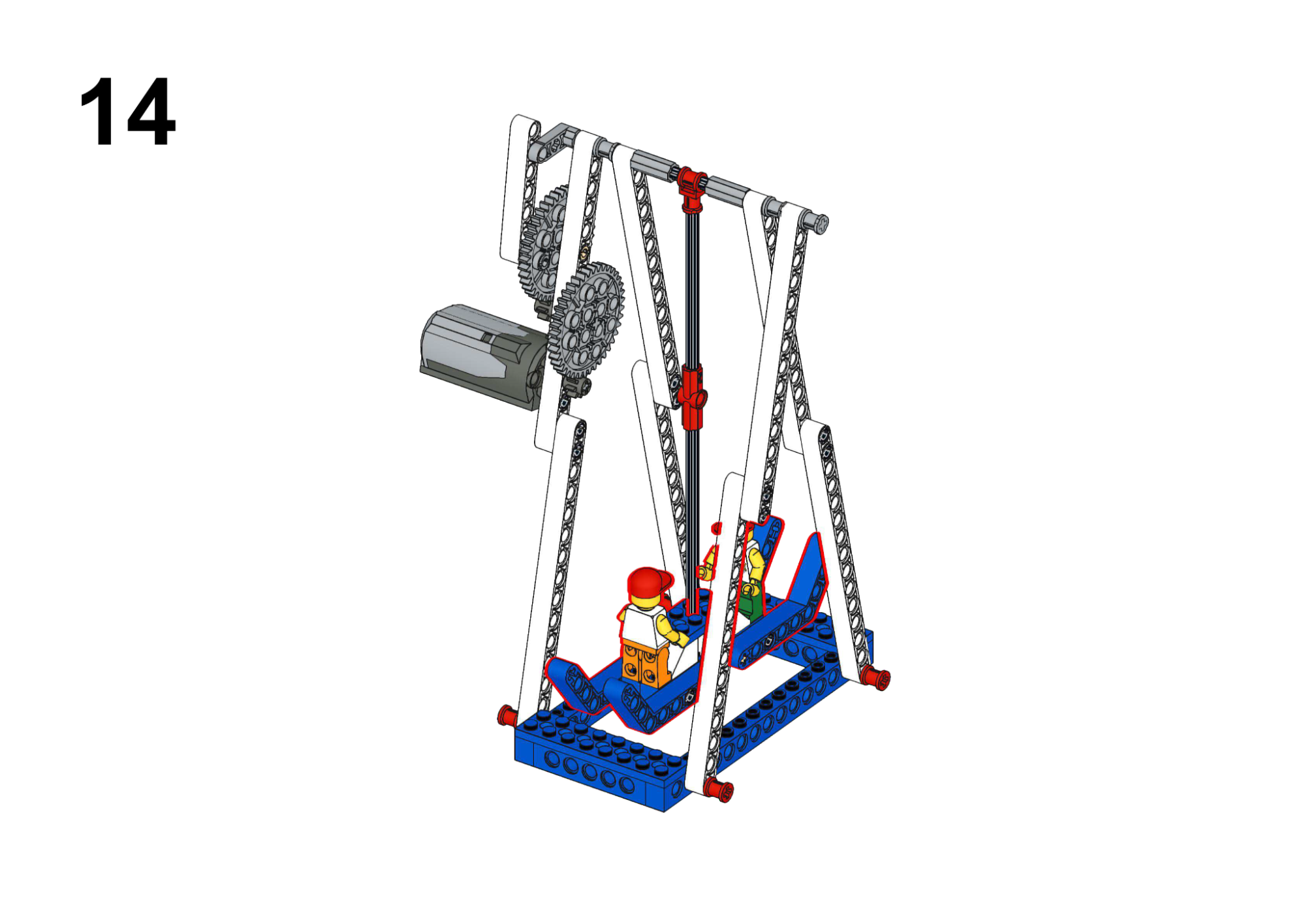
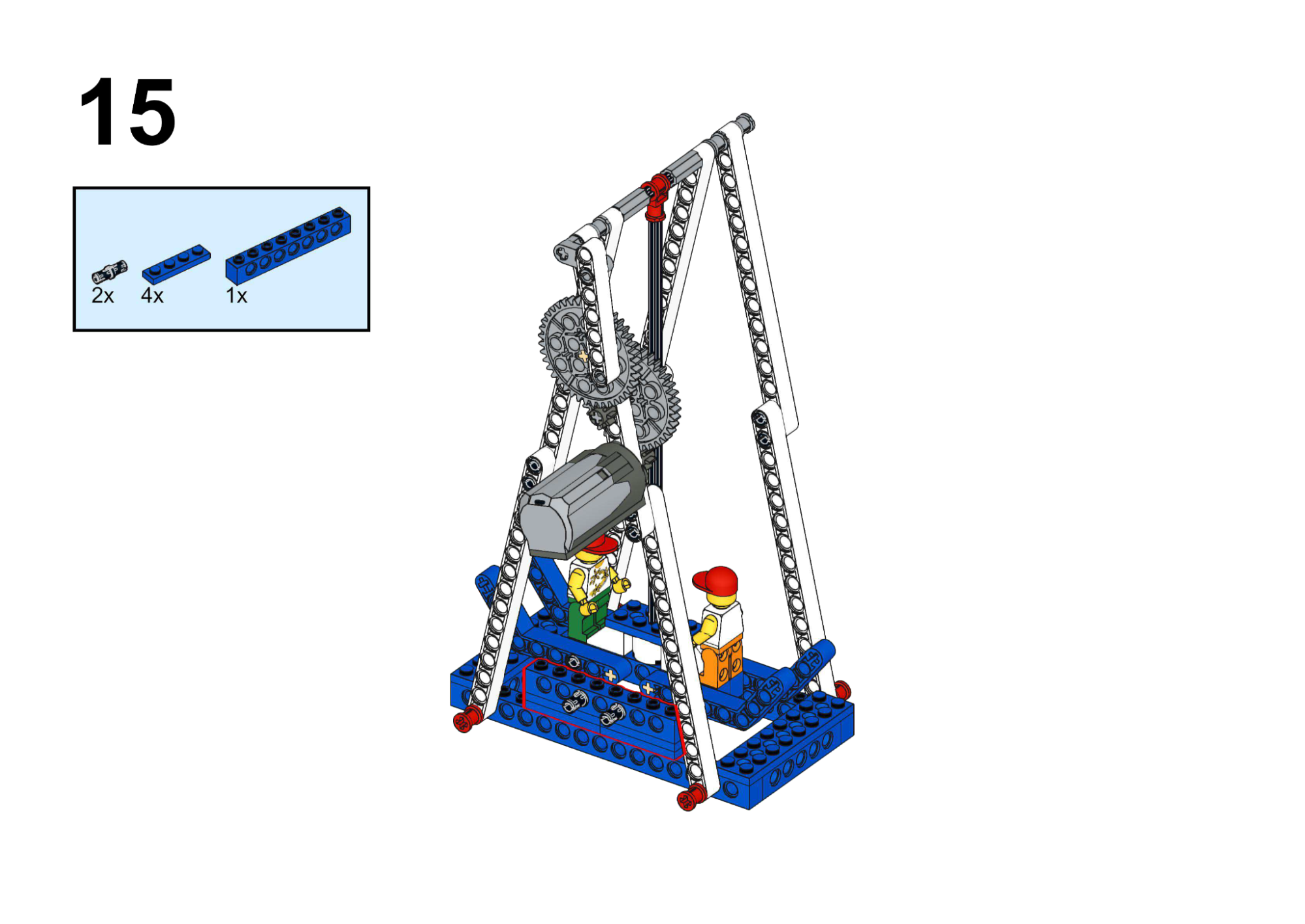
Completed Construction:
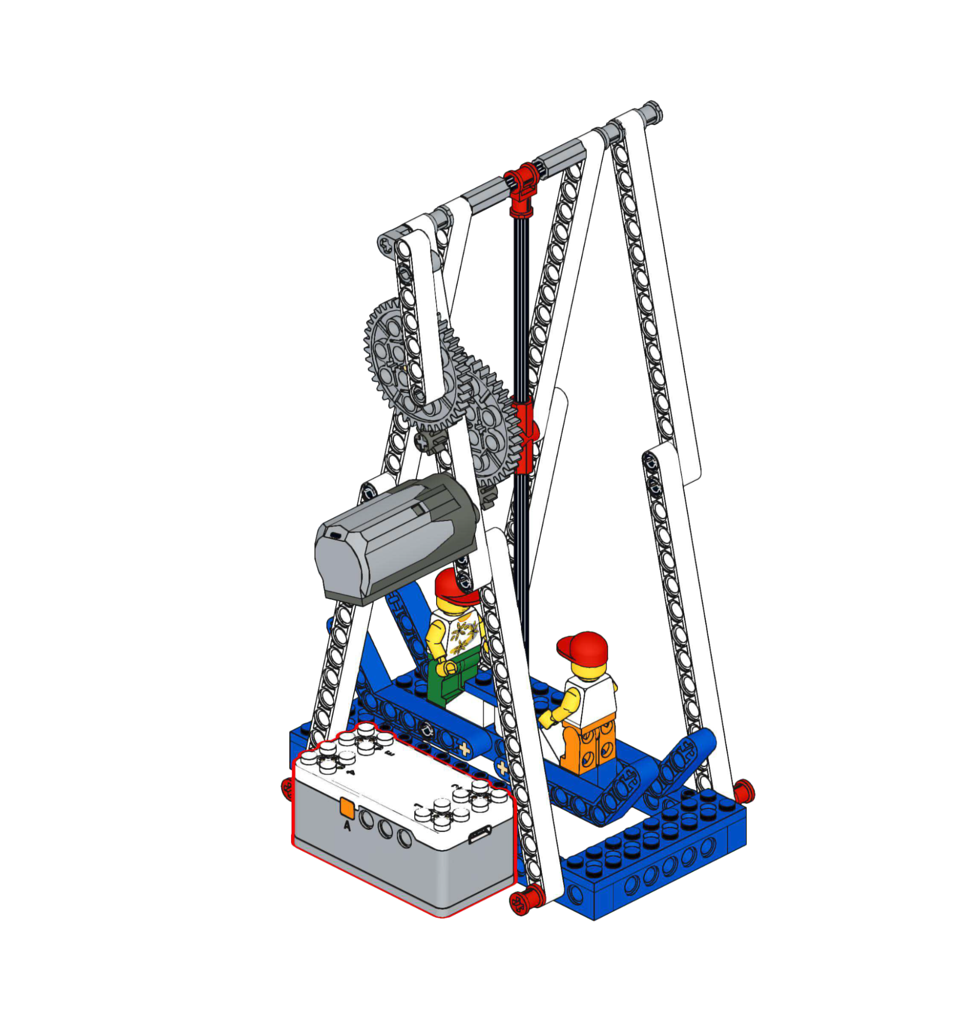
Hardware & Wiring
- Motor: Port 1
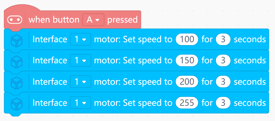
Mind+ Logic
- When Button A is pressed:
- Run Motor speed 100 for 3 seconds.
- Then speed 150 for 3 seconds.
- Then speed 200 for 3 seconds.
- Then speed 255 for 3 seconds.
- Allow the crank-link mechanism to translate speed into swing amplitude.
View Completed Program
Goal
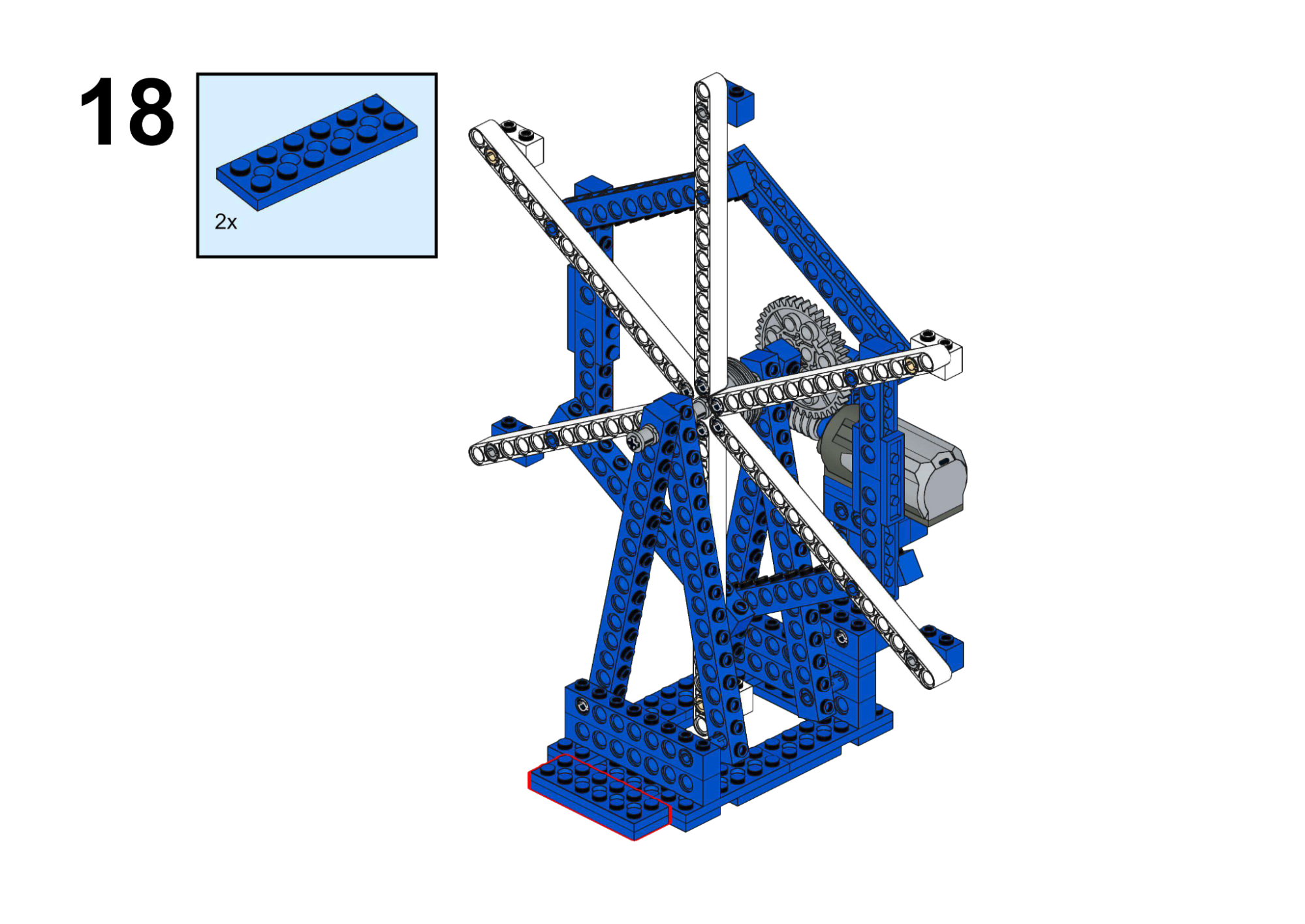
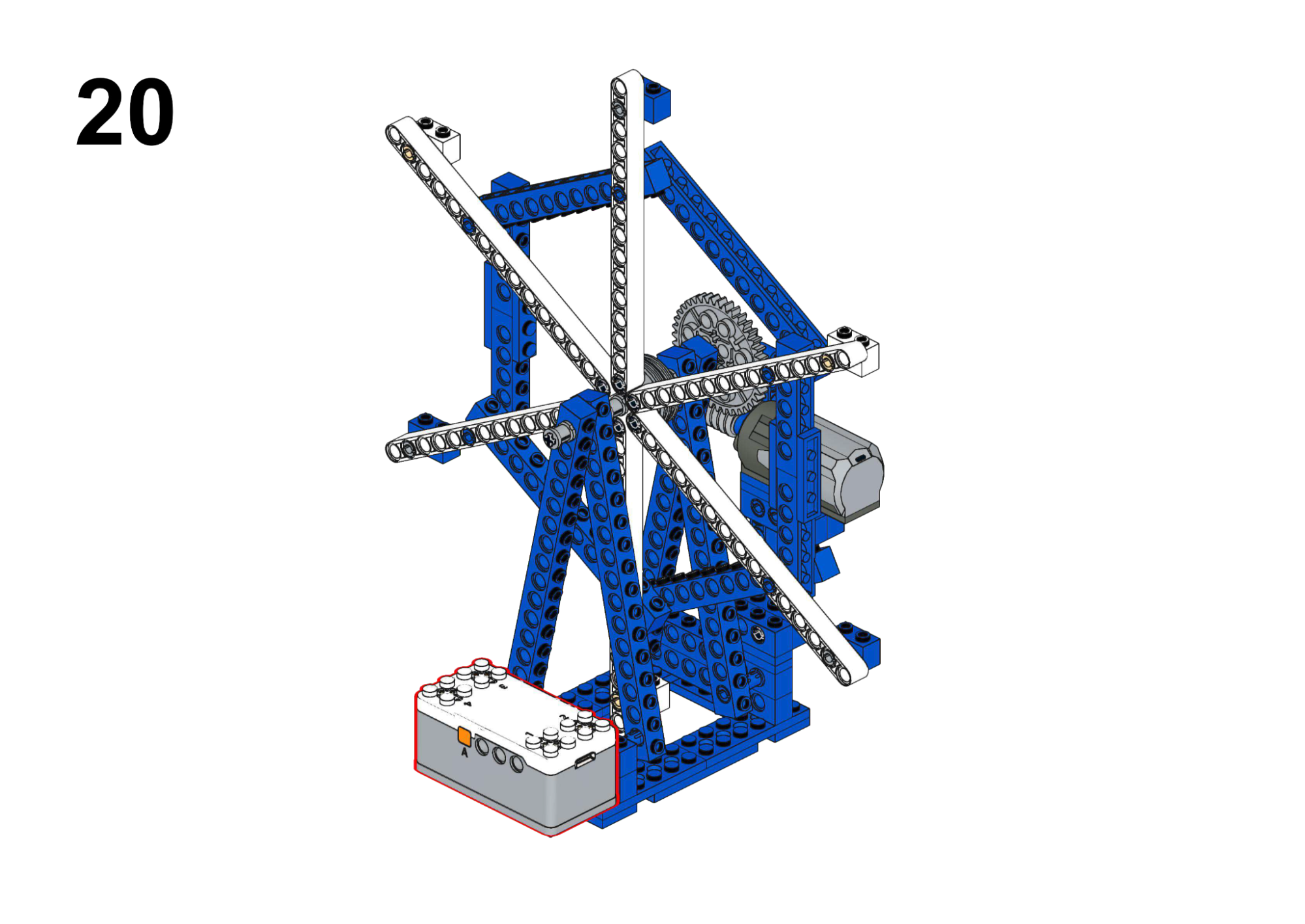
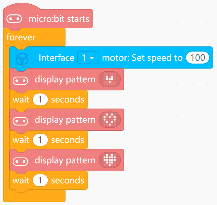
Rotate the wheel while showing different icons on the LED matrix.
View Assembly Instructions
Hardware & Wiring
- Motor: Port 1
Mind+ Logic
- In forever:
- Set Motor (Port 1) speed to a moderate value (e.g. 100).
- Show icon 1, wait 0.5 seconds.
- Show icon 2, wait 0.5 seconds.
- Show icon 3, wait 0.5 seconds.
- The program will loop through these icons to simulate changing views.
View Completed Program
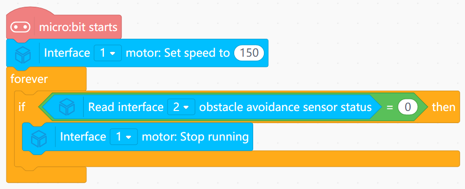
Goal
Drive the cable car along a fixed rope and stop when reaching a “station” marker.
View Assembly Instructions
Hardware & Wiring
- Motor: Port 1
- IR Sensor: Port 2
Mind+ Logic
- At startup:
- Begin Motor (Port 1) forward motion (speed 150).
- In forever:
- Read obstacle avoidance sensor (Port 2) state.
- If state indicates obstacle or station (state = 0):
- Stop motor.
- To restart: move the cable car manually, reset board, or add button logic.
View Completed Program
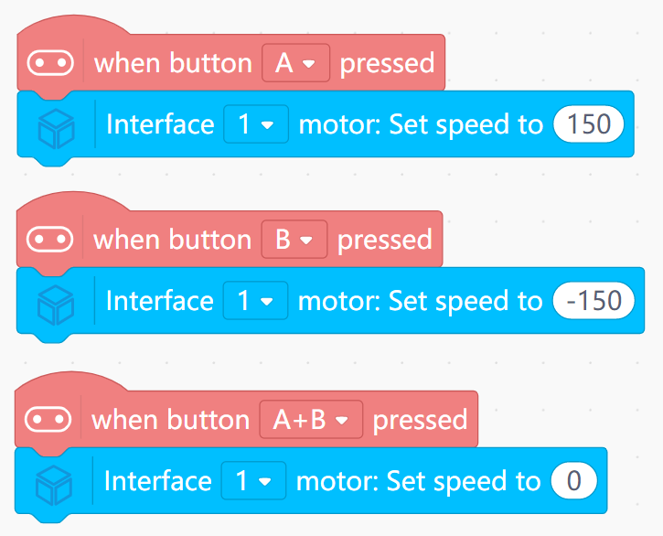
Goal
Learn to control rotation direction with Buttons A and B, and stop with A+B.
View Assembly Instructions
Hardware & Wiring
- Motor: Port 1
Mind+ Logic
- Event “Button A pressed”: set Motor (Port 1) speed to 150.
- Event “Button B pressed”: set speed to -150.
- Event “Button A+B pressed”: set speed to 0.
View Completed Program
4. Engineering Series (Industrial Automation)
Focus: Complex machinery, remote control, and automation logic.
Goal
- Simulate a sewing machine with multiple speed gears.
- Show current gear number on LED matrix.
View Assembly Instructions
Hardware & Wiring
- Motor: Port 1
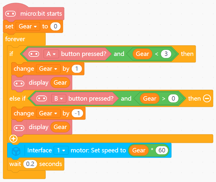
Mind+ Logic
- Create variable
Gearwith initial value 0. - If button A is pressed and
Gear < 3:- Increase
Gearby 1. - Display
Gear.
- Increase
- If button B is pressed and
Gear > 0:- Decrease
Gearby 1. - Display
Gear.
- Decrease
- In forever:
- Set Motor (Port 1) speed to
Gear * 60. - Wait 0.2 seconds.
- Set Motor (Port 1) speed to
View Completed Program
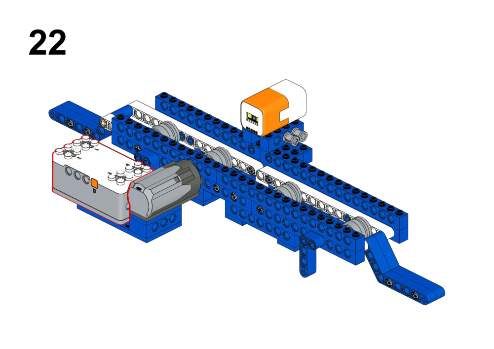
Goal
Move objects in opposite directions using a single conveyor belt motor.
View Assembly Instructions
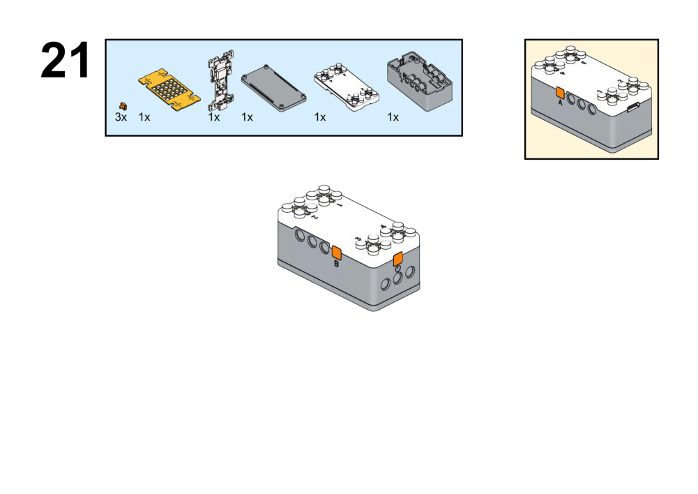
Hardware & Wiring
- Color Sensor: Port 4
- Motor: Port 1
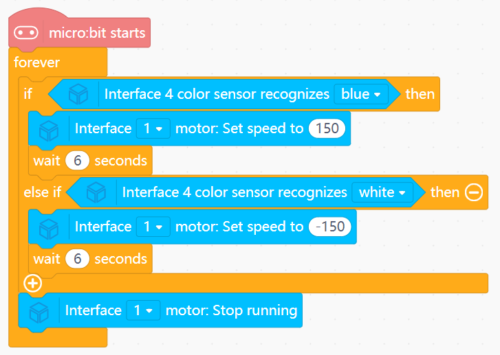
Mind+ Logic
- In forever:
- Read color from sensor.
- If color == BLUE:
- Run Motor (Port 1) forward (speed 150).
- Wait 6 seconds.
- Else if color == WHITE:
- Run Motor reverse (speed -150).
- Wait 6 seconds.
- Else:
- Stop motor.
View Completed Program
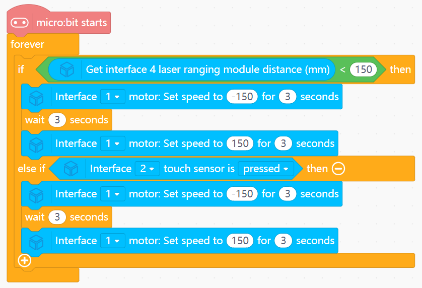
Goal
- Open the door when someone approaches or when a button inside is pressed.
- Automatically close after 3 seconds.
View Assembly Instructions
Hardware & Wiring
- Laser: Port 4
- Touch: Port 2
- Motor: Port 1
Mind+ Logic
- In forever:
- Read distance value from laser sensor and pressed value from touch sensor.
- If
distance < 150OR the touch sensor is pressed:- Run Motor (Port 1) to open door (speed -150) for 3 seconds.
- Wait 3 seconds.
- Run motor to close door (speed 150) for 3 seconds.
View Completed Program
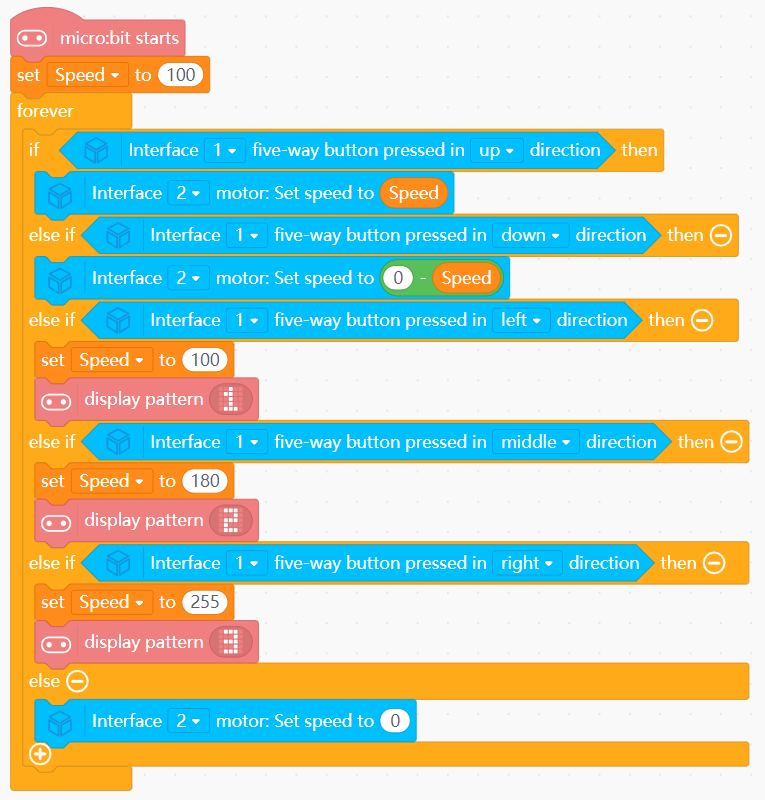
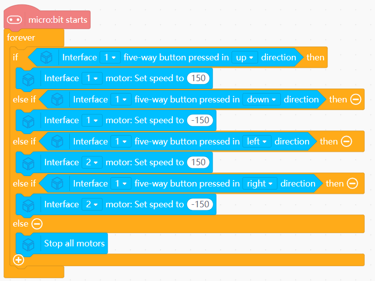
Goal
- Raise and lower the ladder and change its speed using a joystick.
- Display current gear on the LED matrix.
View Assembly Instructions


Hardware & Wiring
- Joystick: Port 1
- Motor: Port 2
Mind+ Logic
- Create the variable
Speedwith initial value 100. - UP/DOWN joystick:
- UP → motor forward (raise) using
Speed. - DOWN → motor reverse (lower) using
Speed.
- UP → motor forward (raise) using
- Five-direction control:
- Up → Set motor (Port 2) speed to
Speed. - Down → Set motor speed to
0 - Speed. - Left → Set
Speedto 100 and display pattern1on screen. - Middle → Set
Speedto 180 and display pattern2on screen. - Right → Set
Speedto 255 and display pattern3on screen.
- Up → Set motor (Port 2) speed to
- Else: Stop motor.
View Completed Program
Goal
Control both boom lifting and hook/rotation with a single joystick.
View Assembly Instructions
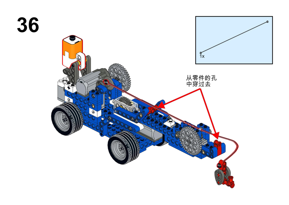
Hardware & Wiring
- Joystick: Port 1
- Motor 1: Port 2
- Motor 2: Port 3
Mind+ Logic
- In forever:
- Up → Set Motor 1 speed to 150.
- Down → Set Motor 1 speed to -150.
- Left → Set Motor 2 speed to 150.
- Right → Set Motor 2 speed to -150.
- Else: Stop all motors.
View Completed Program
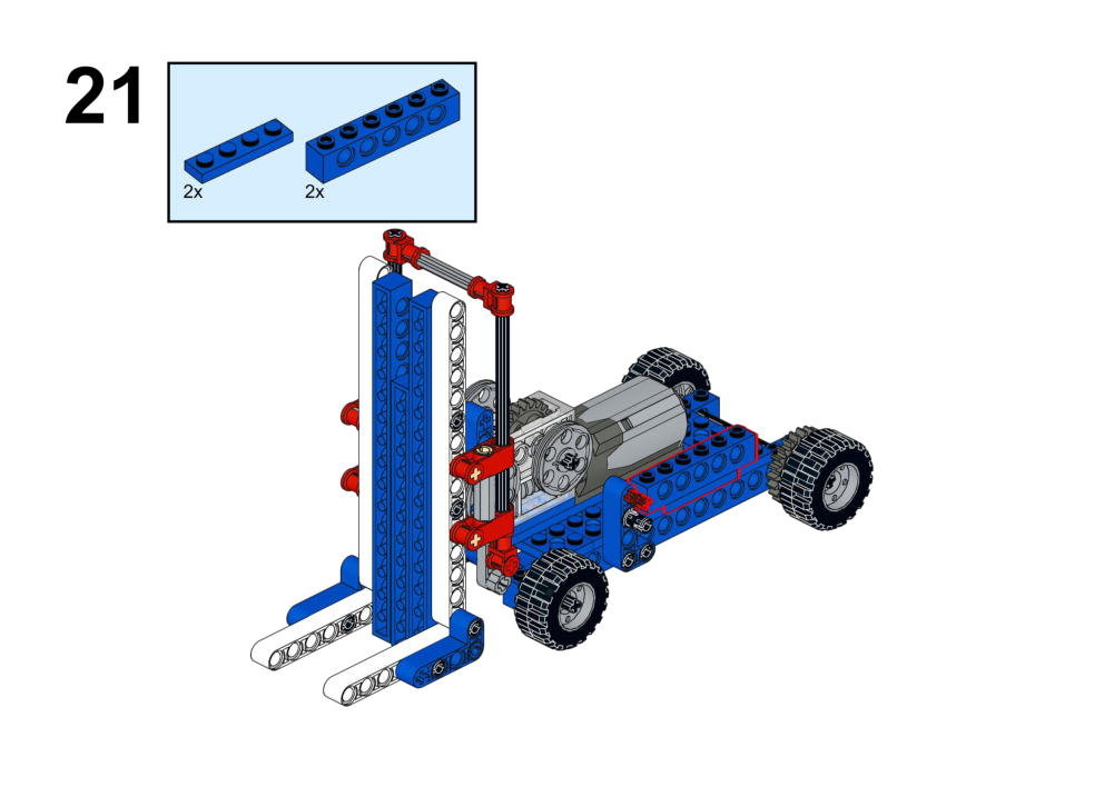
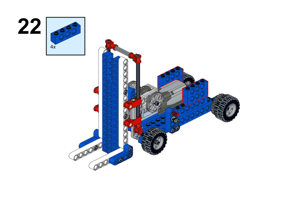
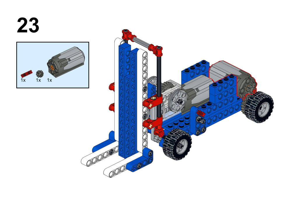
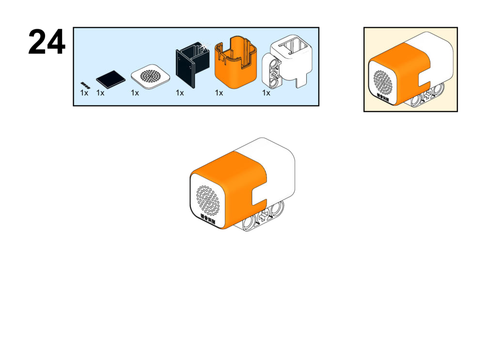
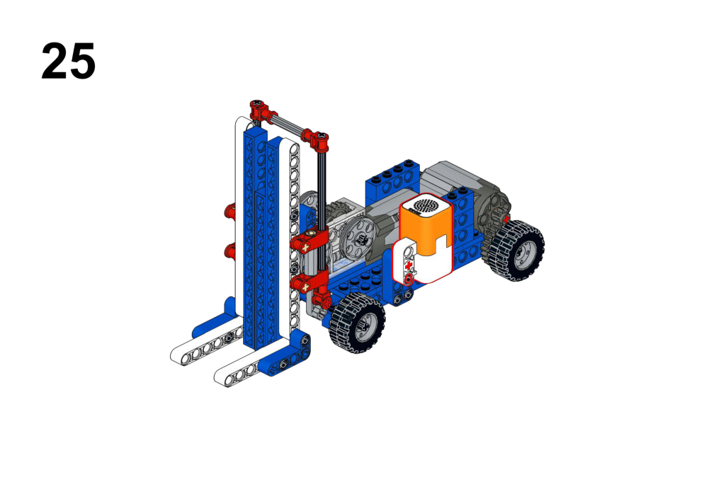
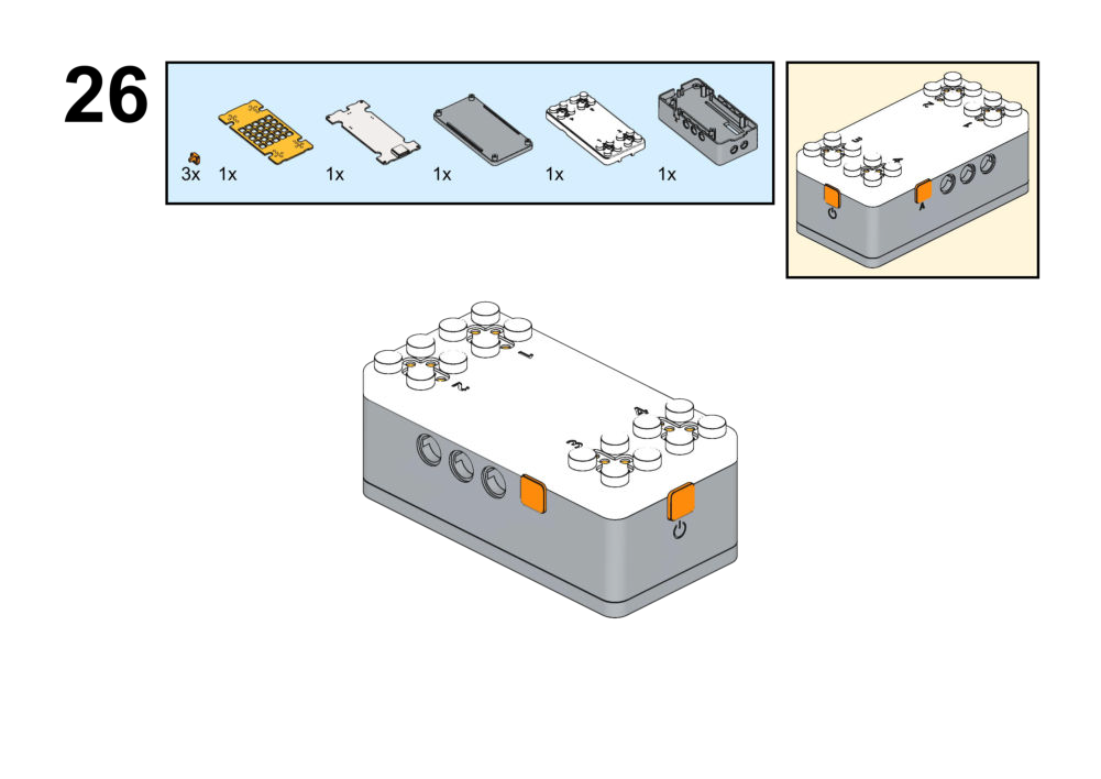
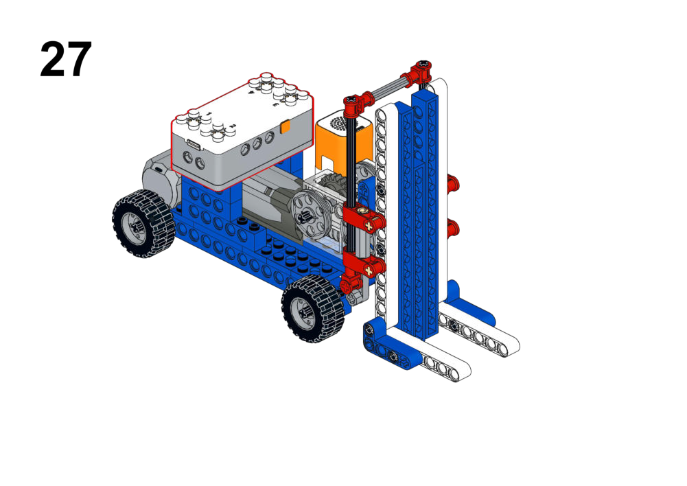
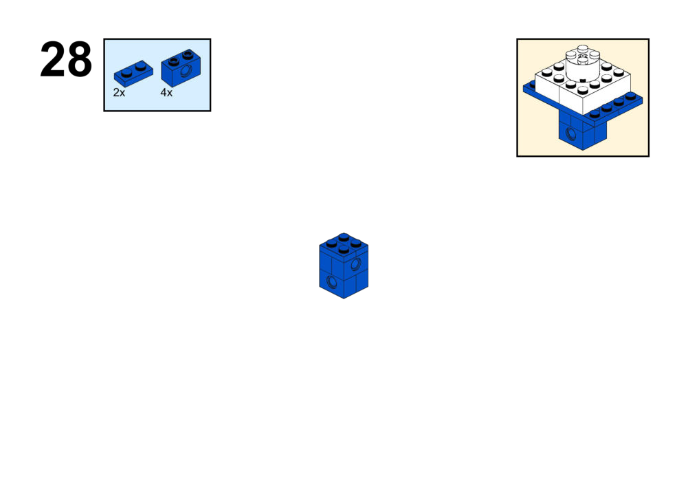
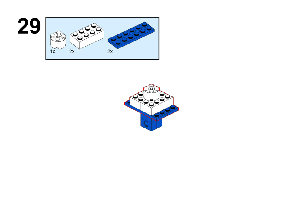
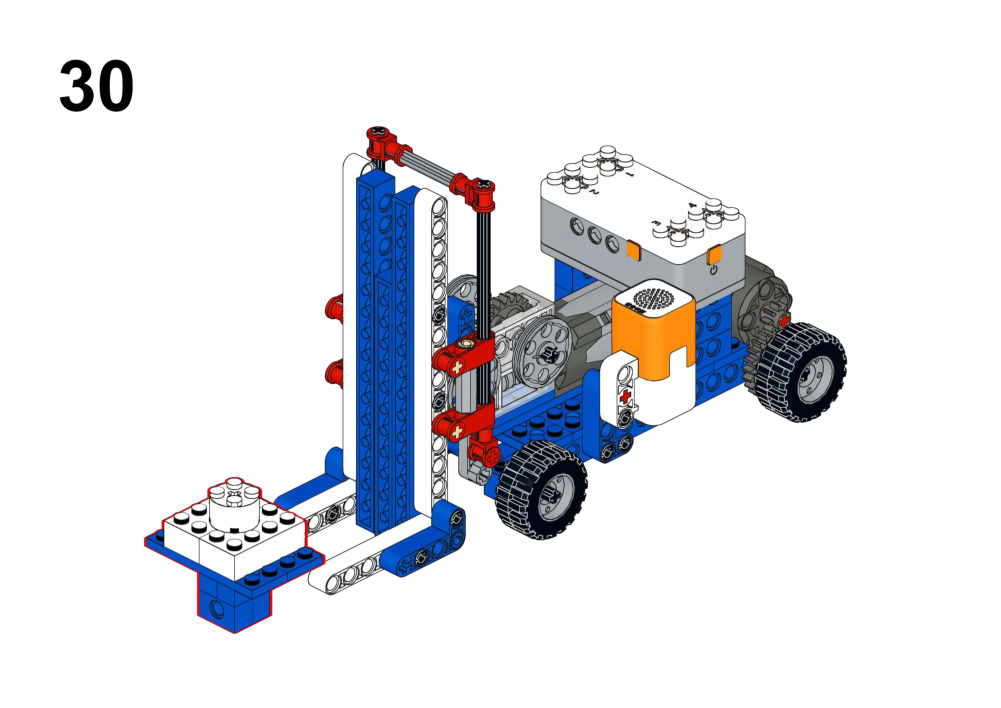
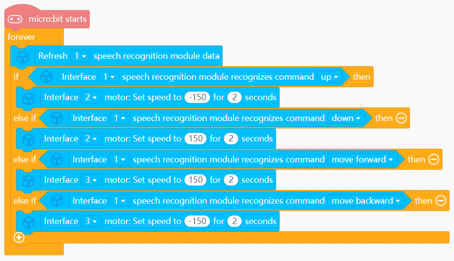
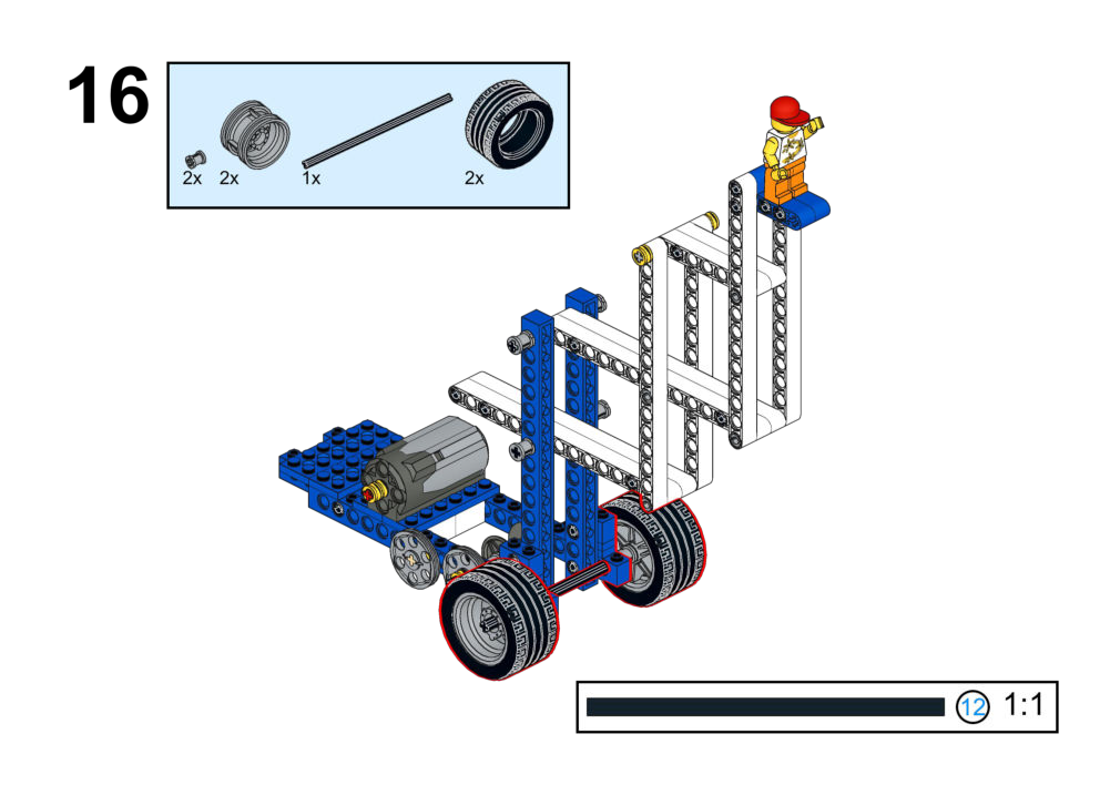
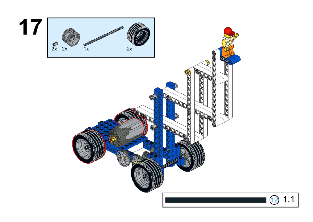
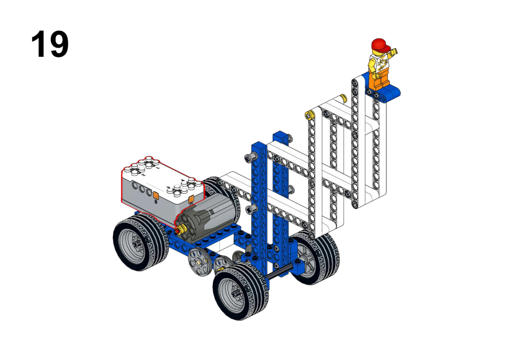
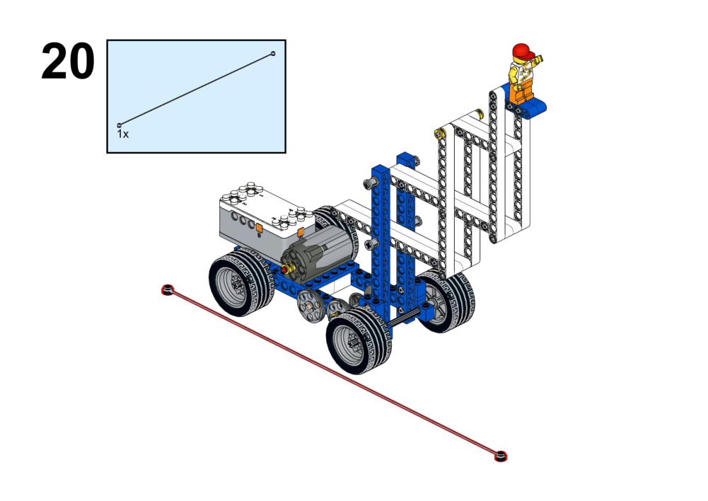
Goal
Use voice commands to control both the fork and the vehicle motion.
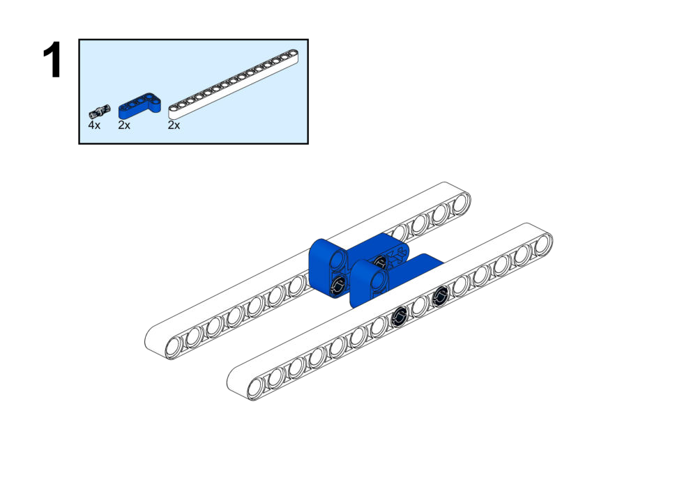
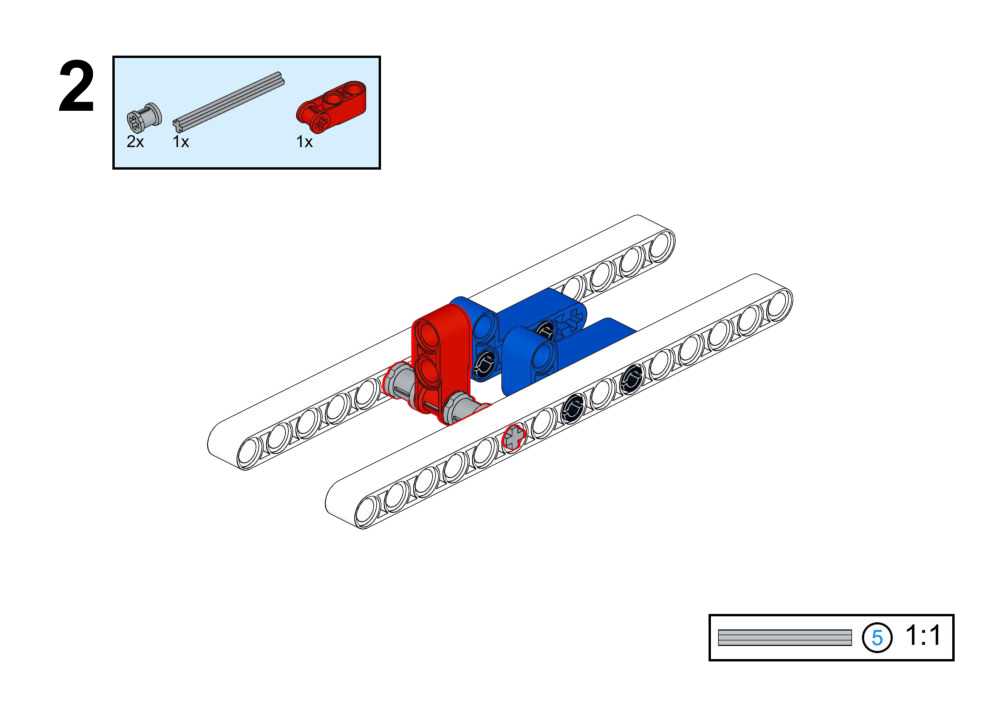
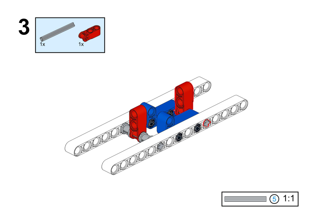
View Assembly Instructions
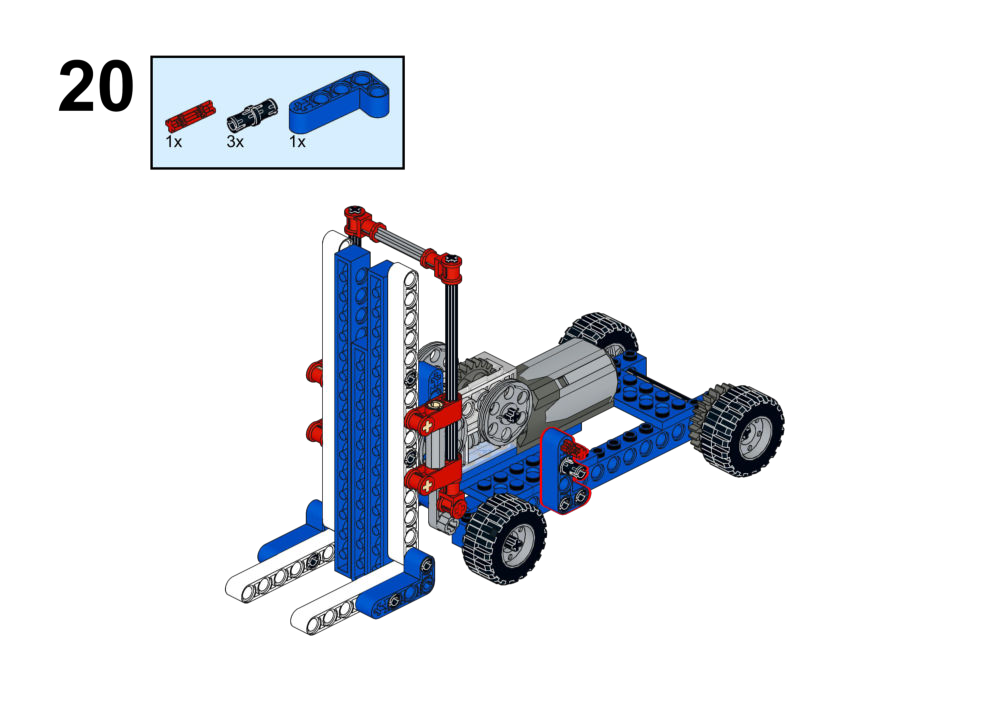
Hardware & Wiring
- Voice Module: Port 1
- Fork Motor: Port 2
- Drive Motor: Port 3
Mind+ Logic
- In forever:
- Refresh voice module (Port 1) and read current command.
- If command = “up” → run Motor 2 at speed -150 for 2 seconds.
- If command = “down” → run Motor 2 at speed 150 for 2 seconds.
- If command = “forward” → run Motor 3 at speed 150 for 2 seconds.
- If command = “backward” → run Motor 3 at speed -150 for 2 seconds.
View Completed Program
Goal
Design your own control method (Button, Joystick, or Voice) to operate the scissor lift mechanism safely.
View Assembly Instructions
Hardware & Wiring
- Motor → chosen port (e.g. Port 2).
- Sensor input → any available port depending on chosen module.
Mind+ Logic
- Pick control strategy, e.g.:
- Buttons to raise/lower.
- Joystick for continuous variable control.
- Voice commands for up/down/stop.
- Implement:
- Up command → Motor forward.
- Down command → Motor reverse.
- Stop condition (e.g. button release or limit sensors) → Motor 0.
Goal
Combine multiple motors and inputs to control the boom, arm, and bucket simultaneously.
View Assembly Instructions
Hardware & Wiring
- Multiple motors → different ports for each joint.
- Controllers: joystick, buttons, or voice module per student’s design.
Mind+ Logic
- Decide control mapping:
- For example, joystick axes for boom/arm, buttons for bucket open/close.
- For each input:
- Read value/direction.
- Set corresponding motor speed and direction.
- Optional: add safety limits or automatic reset positions.
5. Technical Summary
Hardware Pinout Reference
- Motors: DC Geared Motors (-255 to 255 speed).
- Port 4: Specialized for Laser Range & Color Sensor.
- Ports 1-3: General I/O for Buttons, Touch, Sound, Light, IR, LED, etc.
- Battery: 18650 Li-ion (Rechargeable).